A421 Series Electronic Temperature Controls with Off-Cycle Defrost Installation Instructions
6
Setup and Adjustments
Front Panel
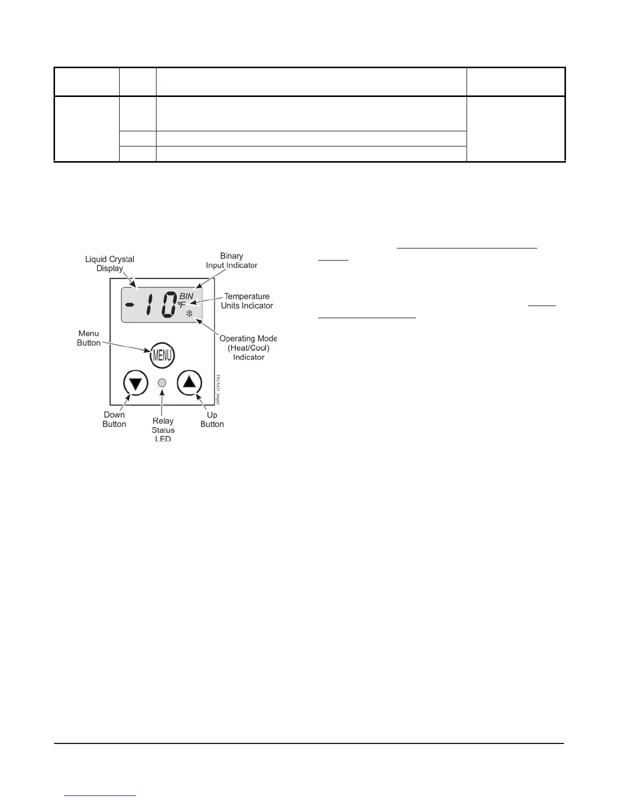
The front panel of the A421 Series Electronic
Temperature Control has a simple LCD and a
three-button user interface (Figure 5).
Liquid Crystal Display
The A421 Series Control has a backlit LCD screen
(Figure 5). The LCD brightness is adjustable. During
normal operation, the LCD displays the Main screen,
which provides following information:
• the temperature sensed at the A99 sensor
• the selected temperature units (°F or °C)
• the mode of operation (Flame = Heating mode,
Snowflake = Cooling mode)
• Binary Input status (BIN) when a (user-supplied)
momentary switch is connected and closed to
manually start or stop a defrost cycle.
During setup and adjustment, the LCD displays the
parameter code screens and the parameter value
screens. See the A421 Control Parameter Setup
Menus on page 9 for more information.
Three-Button Touchpad
The touchpad has three buttons for setup and
adjustment of the A421 control (Figure 5). See Menu
Navigation Guidelines on page 9 for more information
on using the three-button touchpad.
Relay Status LED
The green LED on the front panel illuminates when the
SPDT output relay is energized and the LC and LNO
contacts are closed. See Figure 5.
Parameter Codes and Modes of Operation
Relay Off Temperature (OFF): Select the temperature
at which the output relay de-energizes, the LC to LNO
relay contacts open (cutout), and the green LED goes
off. The range of usable temperature values is
-40 to 212 (°F) or -40 to 100 (°C) in 1° increments.
Relay On Temperature (On): Select the temperature
at which the output relay energizes, the LC to LNO
relay contacts close (cut in), and the green LED lights.
The range of usable temperature values is
-40 to 212 (°F) or -40 to 100 (°C) in 1° increments.
Heating or Cooling Mode of Operation: When you
select the preferred On and OFF values, the control
automatically determines the mode of operation and
displays the proper mode icon on the Main screen.
Note: The A421 Series controls do not have jumpers
for setting up the heating or cooling mode.
TB3 BIN Detects a switch closure between the BIN and COM terminals and
manually starts or stops a defrost cycle. (This is now the default behavior
for the binary input.)
22 AWG (0.34 mm
2
)
stranded, shielded
cable recommended
COM Connects low-voltage common from the sensor and binary input.
SEN Connects low-voltage input signal wire from control sensors.
Table 2: A421 Control Wiring Terminals and Wire Size Information (Part 2 of 2)
Terminal
Block
Label Description, Function, and Requirements Recommended
Wire Sizes
Figure 5: A421 Control Front Panel with LCD
and Three-Button User Interface

 Loading...


