A421 Series Electronic Temperature Controls with Off-Cycle Defrost Installation Instructions
7
The heating or cooling mode is determined by the On
and OFF value relationship as follows:
• OFF > On = Heating mode = Flame icon
• OFF < On = Cooling mode = Snowflake icon
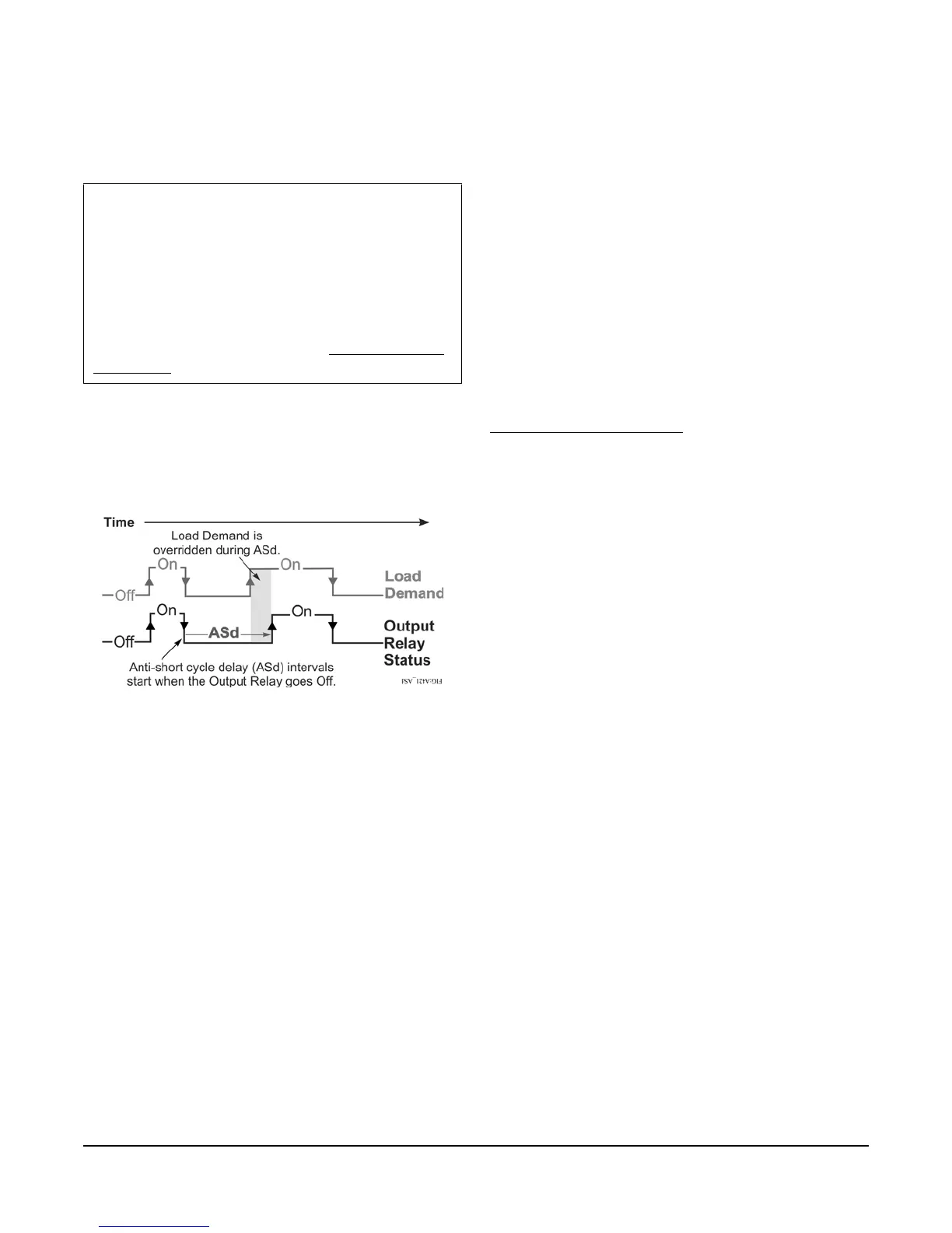
Anti-Short Cycle Delay (ASd): Select the minimum
time that the output relay remains off (de-energized)
before the next on-cycle can start. The ASd interval
overrides any load demand (On) and does not allow
the output relay to go on until the selected ASd interval
has elapsed. See Figure 6.
Anti-short cycle delay is typically used for refrigeration
applications to allow the system pressure to equalize
before restarting the compressor.
Note: When the ASd value is greater than 0, the delay
interval is initiated every time that the A421 control is
powered on and every time that a defrost cycle begins.
When the ASd interval is activated, the temperature
sensed at the A99 sensor and the parameter code ASd
flash (alternately) on the LCD. The ASd interval can be
set from 0 to 12 minutes, in 1-minute increments.
Sensor Failure Mode (SF): Select how the control’s
output relay operates (energized or de-energized) in
the event of a sensor or sensor wiring failure. When the
control detects a sensor circuit failure, the output relay
operates in the selected sensor failure mode. The LCD
flashes SF and OP if the sensor circuit is open or SF
and SH if the sensor circuit is shorted.
Temperature Units (Un): Select the desired
temperature scale for your application. Select either the
Fahrenheit (°F) or Celsius (°C) temperature scale.
Note: After changing the temperature units value
(Un), confirm that the temperature values for the other
parameter codes are still correct for your application.
Low Temperature Stop (LtS): Select the lowest
temperature value that the On/OFF control band can
be adjusted to when control adjustment is restricted.
High Temperature Stop (HtS): Select the highest
temperature value that the On/OFF control band can
be adjusted to when control adjustment is restricted.
Restricted Adjustment Mode: The HtS and LtS
values define the restricted adjustment temperature
range and are enforced only when the A421 control is
set to the restricted adjustment mode (Figure 12). See
Restricting User Adjustment
.
Note: We recommend leaving HtS and LtS at their
default values, unless you intend to use the restricted
adjustment mode.
Note: If you use the Temperature Setback feature in
the Restricted Adjustment Mode, the effective On and
OFF setback values (On + tSb and OFF + tSb) can be
greater than the selected HtS value or less than the
selected LtS value.
Temperature Setback (tSb): Select a temperature
value for setting back the On and OFF temperature
values. If the Binary Input Mode parameter is set to 0
(zero), the (user-supplied) switch is between the BIN
and COM terminals closes:
• the Main screen displays BIN in the upper-right
corner of the LCD.
• the temperature setback feature is enabled and the
control uses the effective On and OFF setback
values (On + tSb and OFF + tSb) to control the
relay.
Note: The control displays only the original On and
OFF values in both the normal and setback modes.
The effective setback On and OFF values (On + tSb
and OFF + tSb) are never displayed on the control
LCD.
The temperature setback adjustment range is from -50
to 50 F° (-30 to 30 C°). Typically, heating applications
require a negative temperature setback (tSb) value,
and cooling applications require a positive value.
IMPORTANT: During normal operation, just the
On value or just the OFF value on the A421 control
changes the differential between On and OFF, and
can potentially change the mode of operation from
heating to cooling or cooling to heating. To maintain
a constant differential between On and OFF, you
must adjust both the On value and OFF value by an
equal number of degrees; or set up the control in the
Restricted Adjustment Mode. See Restricting User
Adjustment.
Figure 6: Anti-Short Cycle Delay

 Loading...


