A421 Series Electronic Temperature Controls with Off-Cycle Defrost Installation Instructions
8
Sensor Offset Adjustment (So): Sensor offset allows
you to compensate for any difference between the
displayed temperature value and the temperature
sensed at the A99 sensor. Select a temperature value
to offset the temperature displayed on the LCD from
the temperature sensed at the sensor. The sensor
offset adjustment range is from -5 to 5 F° (-3 to 3 C°) in
1° increments.
Backlight Brightness Level (bLL): The backlight
brightness level feature allows you to adjust the LCD
backlight intensity. At level 0 the backlight is off. Level
10 is the brightest backlight setting and the system
default. The selected backlight brightness level is
applied to the LCD during normal operation. When you
enter the programming menus to set up the control or
press any key, the LCD automatically goes to the
brightest level. If no key is pressed for 30 seconds, the
main screen is displayed and the backlight setting
reverts to the selected brightness level.
Defrost Cycle Time (dFt): Select the time (in minutes)
that the defrost cycle overrides On and keeps the relay
Off. The dFt value can be between 1 and 99 (minutes).
When the defrost cycle is On, the control is NOT
running and the LCD displays the following screens:
dEF (defrost mode), minutes remaining, and the
temperature at the sensor. When the dFt is complete,
the control returns to normal (On/Off cycle) operation.
Defrost Interval (dI): Select the time (in hours)
between the start of a defrost cycle and the next
defrost cycle. The dI value can be set to 0 or 2 to 24
(hours).
Note: At the initial power On, the defrost interval (dI)
does NOT have a defrost cycle (dFt). The subsequent
defrost intervals begin with the selected dFt.
Setting the dl value to 0 (zero) eliminates regular/timed
defrost cycles. You can still start or stop a defrost cycle
by setting the SdF parameter or by using the Binary
Input.
Start or Stop Defrost Cycle (SdF): The Start/Stop
Defrost Cycle parameter allows you to start a defrost
cycle, when the control is in normal (On/Off cycle)
operation, or stop a defrost cycle when the defrost
cycle is On.
Change to the SdF value to 1 to start a defrost cycle.
Or, change the value to 0 to stop the defrost cycle, and
return to normal (On/Off cycle) operation.
Binary Input Modes (bIn): The BIN mode allows you
to select how the A421 control operates when a
(user-supplied) binary switch (connected across BIN
and COM on TB3 terminal block) is used with the
control.
Set the BIN parameter to 0 to use the temperature
setback feature. Set the value to 1 and connect a
(user-supplied) momentary contact switch to start or
stop a defrost cycle.
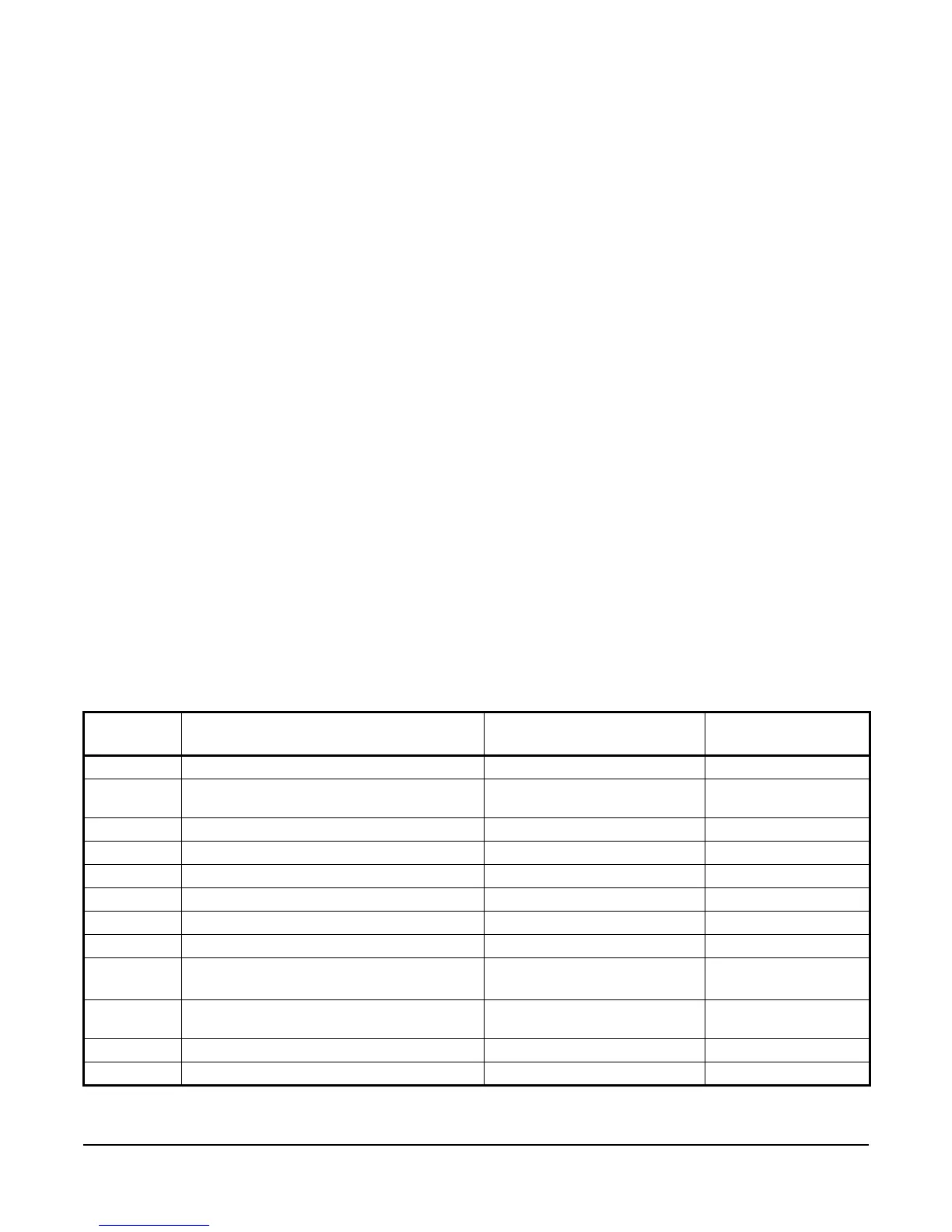
Table 3: Standard Parameter Setup Codes, Descriptions, Range of Values, and Default Values
Parameter
Code
Parameter Description (Menu) Range of Usable Values Factory Default
Value
Un Temperature Units (Advanced only) ºF or ºC ºF
OFF Relay Off Temperature (Basic, Advanced, and
Restricted)
-40 to 212 ºF (-40 to 100 ºC) 25 ºF
On Relay On Temperature (Basic and Advanced) -40 to 212 ºF (-40 to 100 ºC) 30 ºF
ASd Anti-Short Cycle Delay (Basic and Advanced) 0 to 12 (minutes) 0 (minute)
tSb Temperature Setback (Advanced only) -50 to 50 ºF (-30 to 30 ºC) 0 (ºF)
So Sensor Offset Adjustment (Advanced only) -5 to 5 ºF (-3 to 3 ºC) 0 (ºF)
HtS High Temperature Stop (Advanced only) -40 to 212 ºF (-40 to 100 ºC) 212 ºF
LtS Low Temperature Stop (Advanced only) -40 to 212 ºF or -40 to 100 ºC -40 ºF
SF Sensor Failure Action (Basic and Advanced) 0 = output relay de-energized
1 = output relay energized
1 (output relay
energized)
bLL LCD Backlight Brightness Level Adjustment
(Advanced only)
0 to 10; 0 = backlight off, 10 =
brightest backlight setting
10 (brightest backlight)
dFt Defrost Cycle Time (Advanced only) 1 to 99 (minutes) 30 (minutes)
dI Defrost Interval (Advanced only) 0 or 2 to 24 (hours) 8 (hours)

 Loading...


