High-voltage wiring
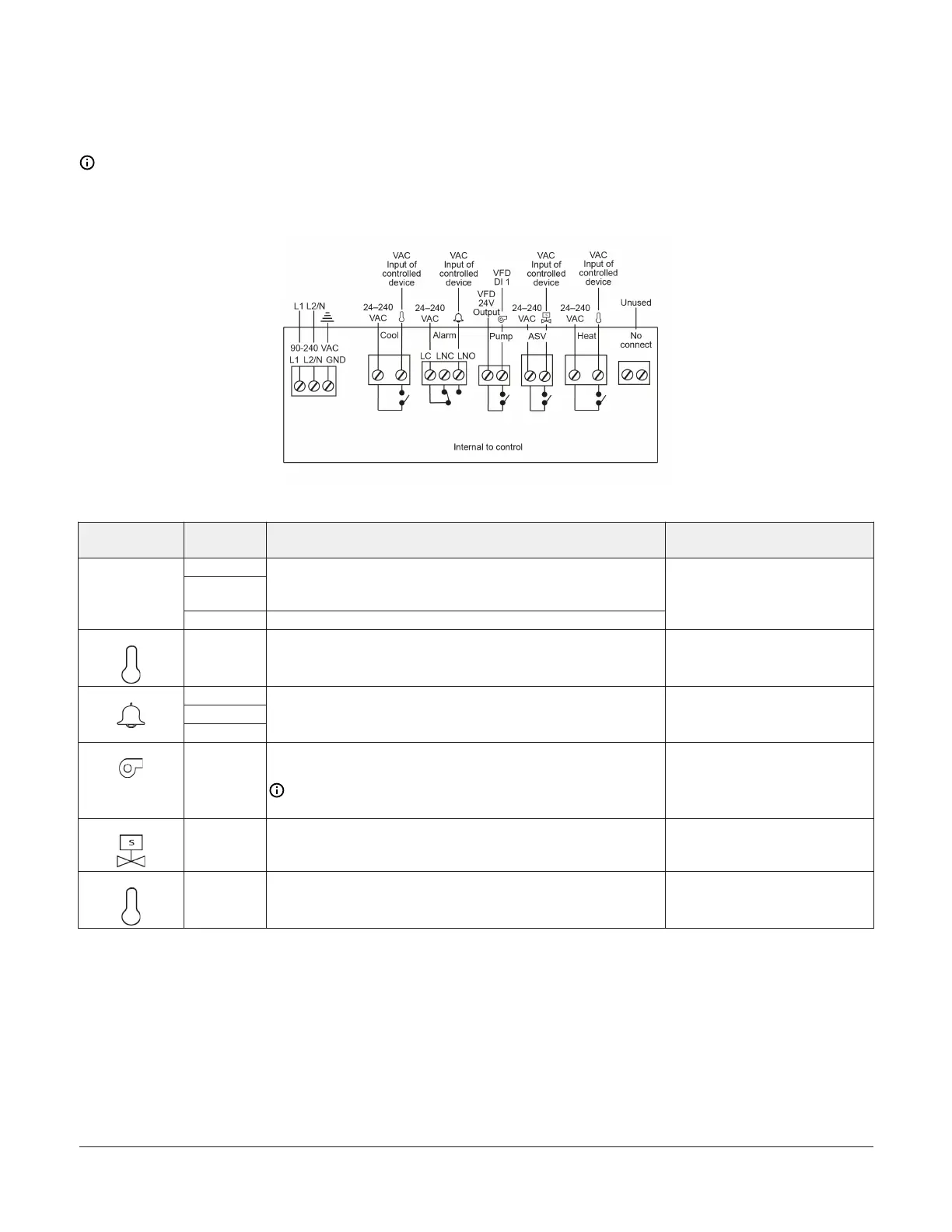
The following figure and table describe the high-voltage wiring terminal blocks, wiring terminal labels, and wire sizes.
See Table 8 to Table 12 for the relay electrical ratings.
Note: When you install the controller, splice the neutral line L2/N from the power input TB1 and connect it to the
neutral input of the controlled device.
Figure 5: A525 Fermentation Controller high-voltage terminal block connections
Table 3: A525 Fermentation Controller high-voltage terminal blocks, terminals, and wire sizes
Terminal block
label
Terminal
voltage
Description, function, and requirements Required wire sizes
L1
L2/N
Two terminals for supply power connection to the A525
Fermentation Controller Requires 90 VAC–240 VAC; 15 VA, (0.25 A
maximum)
90 VAC-
240 VAC
GND Earth ground connection terminal
• 0.75 mm
2
–2.50 mm
2
• (18 AWG–14 AWG)
Cool Two terminals for line-voltage, single-pole, single-throw (SPST),
dry-contact relay control the cooling solenoid valve. The Cool icon
illuminates blue when the cooling relay is energized.
• 1.50 mm
2
– 6.0 mm
2
• (16 AWG–10 AWG)
LC
LNO
Alarm
LNC
The common (LC), normally-open (LNO), and normally-closed (LNC)
terminals for line-voltage, single-pole, double-throw (SPDT), dry-
contact relay control the user-supplied alarm devices.
• 0.30 mm
2
–2.50 mm
2
• (22 AWG–14 AWG)
Pump Two terminals with SPST, dry-contact relay to cycle the circulation
pump on and off. The pump relay connection is optional.
Note: The pump relay does not operate the pump directly.
The VFD uses the pump relay to control the pump operation.
• 0.30 mm
2
–2.50 mm
2
• (22 AWG–14 AWG)
ASV Two terminals for purging excess fermentation gas from the tank.
The ASV relay connects to the solenoid of an air supply valve and is
optional.
• 0.75 mm
2
–2.50 mm
2
• (18 AWG–14 AWG)
Heat Two terminals with SPST, dry-contact relay to control the heating
solenoid valve. The Heat icon illuminates red when the heating
relay is energized.
• 1.50 mm
2
–6.0 mm
2
• (16 AWG–10 AWG)
A525 Fermentation Tank Controller Installation Guide 5

 Loading...