7
Low-voltage terminal blocks and terminals
The following figure and table provide information about the low-voltage wiring terminal blocks and wiring terminal
labels.
Note: For detailed wiring guidelines and instructions, refer to the A5xx Series Wall Mount Refrigeration and
Defrost Controller Installation Instructions (part no. 24-7664-3310).
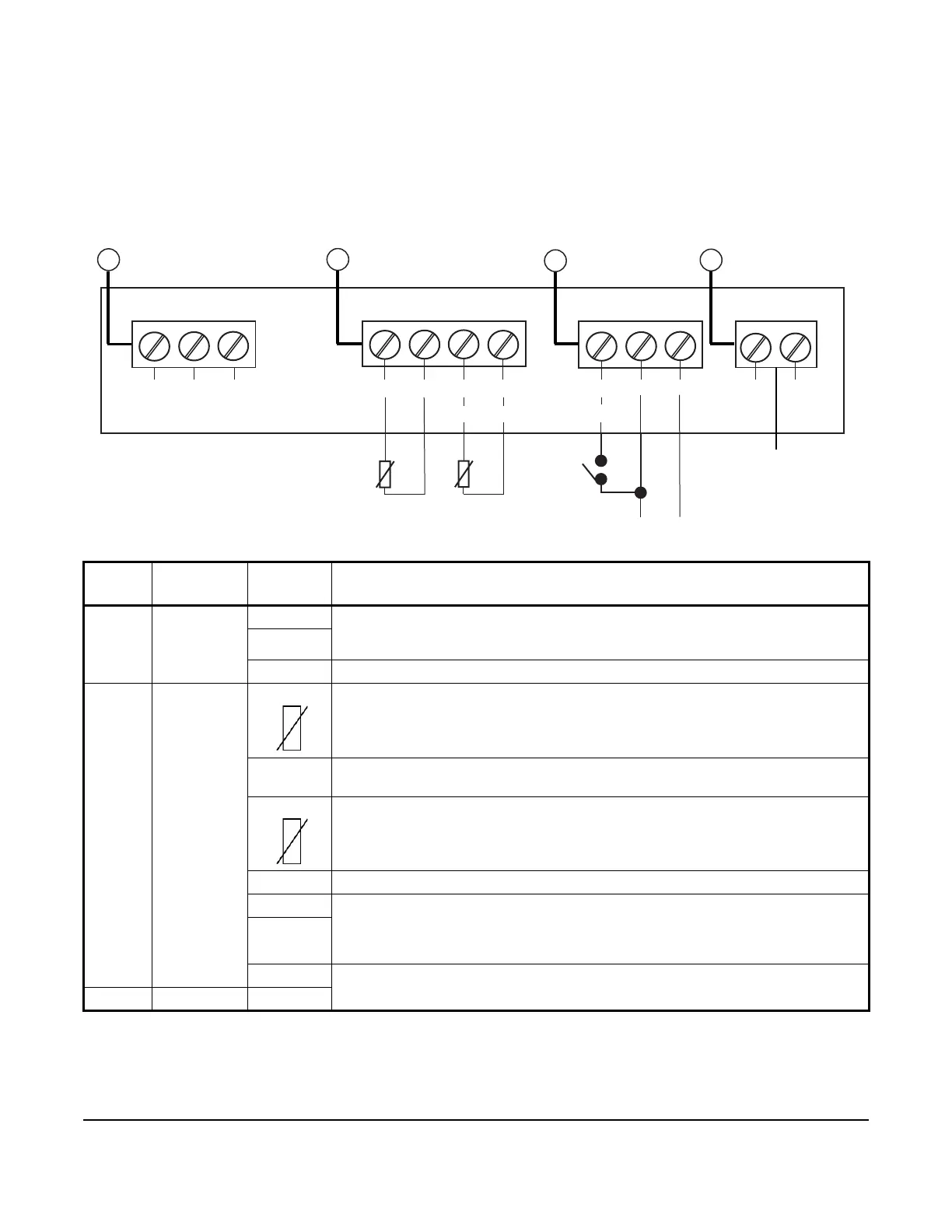
Figure 3: A5xx Controller low-voltage terminal block connections (internal to control)
Table 2: A5xx Controller low-voltage terminal block, terminals, and wire sizes
Callout Terminal
block label
Terminal
label
Description, functions, and requirements
1 RS485
Modbus
A+ The RS485 Modbus communications terminal block provides a restricted connection
to the Modbus connections on an optional Precision Superheat Controller (PSHC).
Do not connect any other Modbus devices to these terminals.
B -
REF The RS485 Modbus signal common or reference
2 Analog
inputs and
outputs
Sn1 Sensor 1 (Sn1) is the main space temperature sensor. Connect either lead from the
sensor to Sn1. Connect the other lead to a common (C) terminal.
Note: Sensor wires for the A5xx Controller are not polarity sensitive.
C The A5xx Controller includes three low-voltage common terminals. All of the low-
voltage C terminals are connected together on the PC board.
Sn2 The evaporator temperature sensor. Connect either lead from the sensor to Sn2.
Connect the other lead to a C terminal.
Note: Sensor wires for the A5xx Controller are not polarity sensitive.
Sn3 Unavailable
UI 4 You can configure universal input 4 (UI 4) or universal input 5 (UI 5) as a 0 VDC to 10
VDC analog input or dry contact binary input. Connect a 0 VDC to 10 VDC input or
binary input to the UI 4 or UI 5 (+) terminal and a C (common/-) on the low-voltage
terminal block.
UI 5
AO1 Analog output is currently not supported on A5xx Controllers. Do not connect to this
terminal.
C
A+
B -
REF
Sn1
Sn2
C
C
Sn3
UI4
C UI5 AO1
C
RS485 MODBUS ANALOG INPUT/OUTPUT
2
2
Analog output
currently not
supported