System 450™ Series Control Modules with Analog Outputs Installation Instructions
4
IMPORTANT: Do not apply power to a C450Y Power Module or the 24 VAC/VDC power source for the System
450 modules before finishing wiring and checking all wiring connections. Short circuits or improperly connected
wires can result in damage to the modules and void any warranty.
IMPORTANT: A System 450 control module and module assembly can be connected to an internal power
source (a System 450 power module) or an external power source (24 VAC/VDC power connected to the 24 V
and COM terminals on the control module), but must not be connected to both power sources simultaneously.
Connecting a control module to both internal and external power sources can damage the modules and void any
warranty.
IMPORTANT: When connecting System 450 compatible sensors with shielded cable to a
System 450 control module, connect the cable shield drain lead to one of the C (common) terminals on the input
sensor terminal block. Do not connect the shield at any other point along the cable. Isolate and insulate the
shield drain at the sensor end of the cable. Connecting a cable shield at more than one point can enable
transient currents to flow through the sensor cable shield, which can cause erratic control operation.
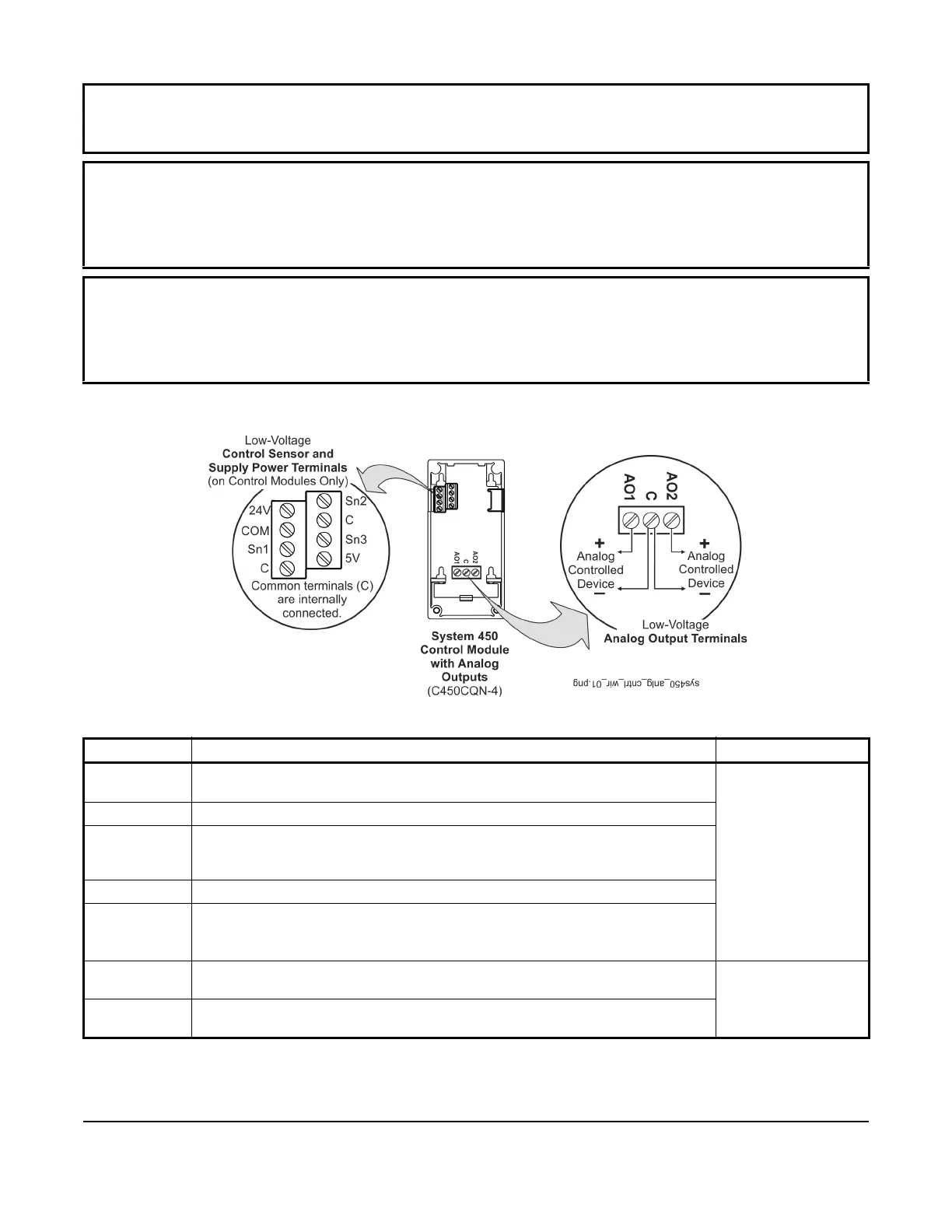
Table 1: System 450 Analog Output Control Module Terminal Wiring Information
Label Terminal Function Wire Sizes
24V Accepts 24 VAC/VDC supply power when a C450YNN power module is not
connected, and provides a power terminal for 24 VAC/VDC (humidity) sensors.
0.08 mm
2
to 1.5 mm
2
28 AWG to 16 AWG
5V Provides 5 VDC power for active sensors.
Sn-1, Sn-2,
Sn-3
Accepts passive or active (0–5 VDC) input signals from control sensors. The
control automatically selects a passive or active sensor circuit for each input based
on the sensors selected in the setup screens.
COM Provides a connection for the 24 VAC/VDC supply common input.
C
(Two
Terminals)
Provides low-voltage circuit Common (C) connections for passive or active sensors
connected to the 5V, Sn1, Sn2, and Sn3 terminals.
Note: The three C terminals are connected internally.
AO1,
AO2
Provides a self-detecting analog output signal in conjunction with the C terminal;
either 0–10 VDC or 4–20 mA.
0.08 mm
2
to 2.5 mm
2
28 AWG to 14 AWG
C Provides a low voltage circuit Common (C) path for the analog outputs (AO1 and
AO2)
Figure 2: C450CxN-4 Wiring Terminals
 Loading...

