System 450™ Series Control Modules with Analog Outputs Installation Instructions
14
If the multi-circuit condensing unit has single speed fan motors, multiple relay outputs can be set up to reference
the high input-signal and System 450 can stage the fans on and off based on the pressure sensed at the coil with
the highest pressure.
If the multi-circuit condensing unit has variable speed fan motors, one or more analog outputs can be set up to
reference the high input-signal and control the fan motor speeds based on the pressure sensed at the coil with the
highest pressure.
Differential Control
System 450 control modules include a Differential Control feature. Differential control is used to monitor and
maintain a given difference in a condition (temperature, pressure, or humidity) between two sensor points within a
system, process, or space.
The Differential Control feature enables a System 450 control system to monitor the temperature, pressure, or
humidity differential between two sensors of the same type (Sn-1 and Sn-2) and control relay or analog outputs
based on the sensed differential value relative to user-selected differential values (dON, dOFF, dSP, and dEP).
When a Differential Control sensor (Sn-d) is set up, the displayed differential sensor value is a calculated variable
value: (Sn-d) = (Sn-1) – (Sn-2).
The Sn-d value appears in the System Status screens as either a temperature differential value (dIFT), pressure
differential value (dIFP), or humidity differential value (dIFH). The unit of measurement associated with the
displayed differential value is determined by the Sn-1 and Sn-2 Sensor Type. See Table 4 on page 9 for Sensor
Types and their units of measurement.
The relay output setup values dON and dOFF are condition differential values. When a relay output is set up for
differential control, System 450 controls the relay state (On or Off) based on the difference between Sn-1 and Sn-2
(Sn-d) relative to the user-selected differential On (dON) and differential Off (dOFF) values.
When an analog output is set up for differential control, System 450 controls the analog signal strength based on
the difference between Sn-1 and Sn-2 (Sn-d) relative to the user-selected differential setpoint (dSP) and differential
endpoint (dEP) values.
Differential Sensor Range of Usable Values
The System 450 Differential Control sensor (Sn-d) value is always equal to Sn-1 minus Sn-2. Depending on the
intended control action of the output, the differential value may be either a positive or negative value. Therefore, the
range of usable values is twice as large as a single sensor, and each Sensor Type has an equal number of positive
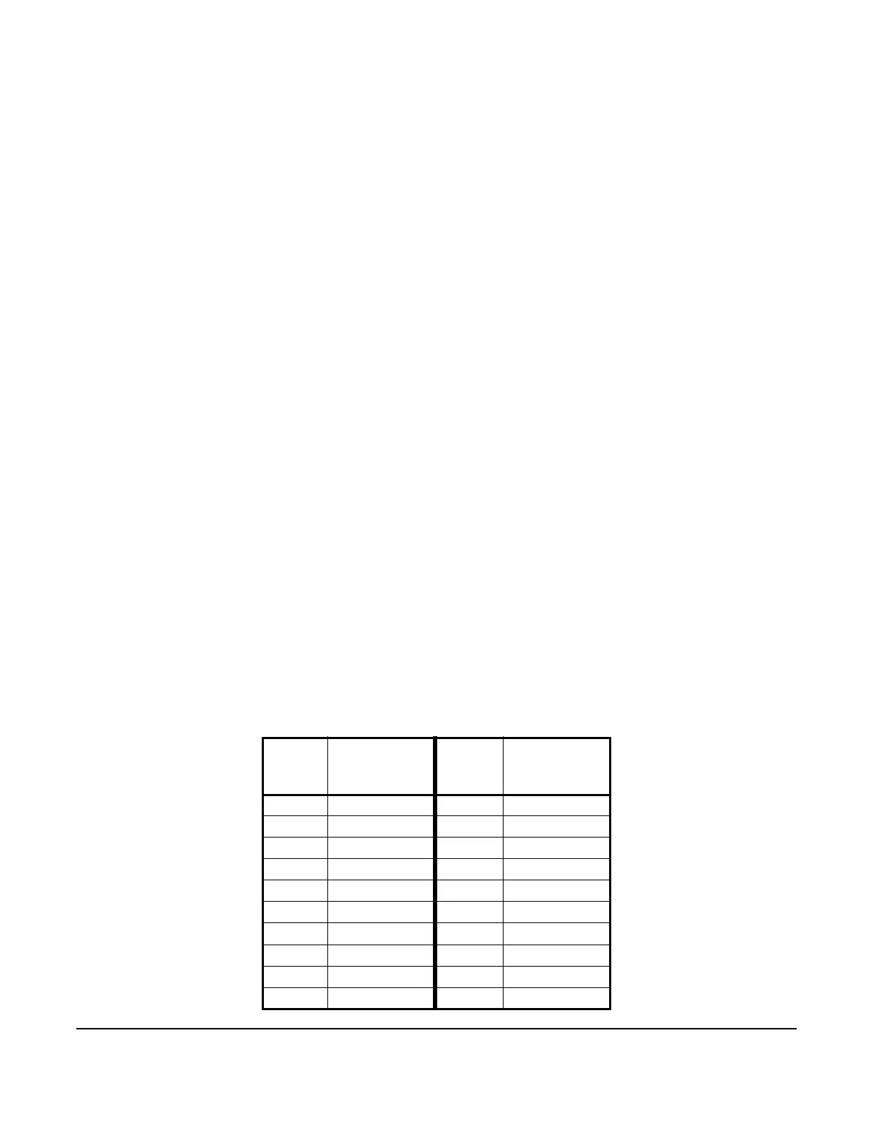
and negative values. See Table 7 for the range of usable values when an output references Sn-d.
Note: Binary Inputs cannot be set up to as a Differential Sensor.
Table 7: Ranges of Usable Values for Sensor Types
in Differential Control Applications
Sensor
Type
Sn-d Range
of Usable
Values
Sensor
Type
Sn-d Range
of Usable
Values
F -290 to 290 P 30 -30.0 to 30.0
C -161.0 to 161.0 P 50 -50.0 to 50.0
rH -95 to 95 P 100 -100.0 to 100.0
P0.25 -0.500 to 0.500 P 110 -110.0 to 110.0
P 0.5 -0.500 to 0.500 P 200 -200 to 200
P 2.5 -2.50 to 2.50 P 500 -500 to 500
P 5 -5.00 to 5.00 P 750 -750 to 750
P 8 -9.00 to 9.00 HIF -380 to 380
P 10 -10.00 to 10.00 HIC -210.0 to 210.0
P 15 -16.0 to 16.0 -- --
 Loading...

