System 450™ Series Control Modules with Analog Outputs Installation Instructions
15
Setting Up System 450 Outputs
After you build and connect power to your control system module assembly, the output numbers and output types
for your control system are automatically assigned in the UI.
Note: You must set up the input sensors for your control system before you can set up the outputs. See Setting
Up System 450 Sensors on page 9 for more information.
To set up System 450 outputs in the UI:
1. Apply power to your module assembly. After the Startup screen appears briefly (displaying the control module
firmware version), the Main screen appears on the LCD.
2. In the Main screen, press any key to exit idle mode, then press and hold
and simultaneously for 5
seconds to access the setup screens and to go to the Sensor Setup Start screen.
3. At the Sensor Setup Start screen, press
repeatedly to scroll through and select the desired Output Setup
Start screen. The Output Setup Start screen indicates the output number and the output type for the selected
output.
4. To set up relay outputs, see Setting Up a Relay Output
and Table 8 for setup information and procedures.
5. To set up analog outputs, see Setting Up an Analog Output
and Table 10 for setup information and procedures.
6. To set up the backlight brightness, see Setting Up the LCD Backlight Brightness
and Table 11 for setup
information and procedures.
Setting Up a Relay Output
Table 8 provides information, procedures, guidelines, and screen examples for setting up relay outputs on System
450 control modules. See Figure 6 on page 26 for example menu flow of the Relay Output 1 setup in Table 8.
Note: The differential sensor, Sn-d, is used to set up analog and relay outputs for Differential Control. See
Differential Control
on page 14 for more information.
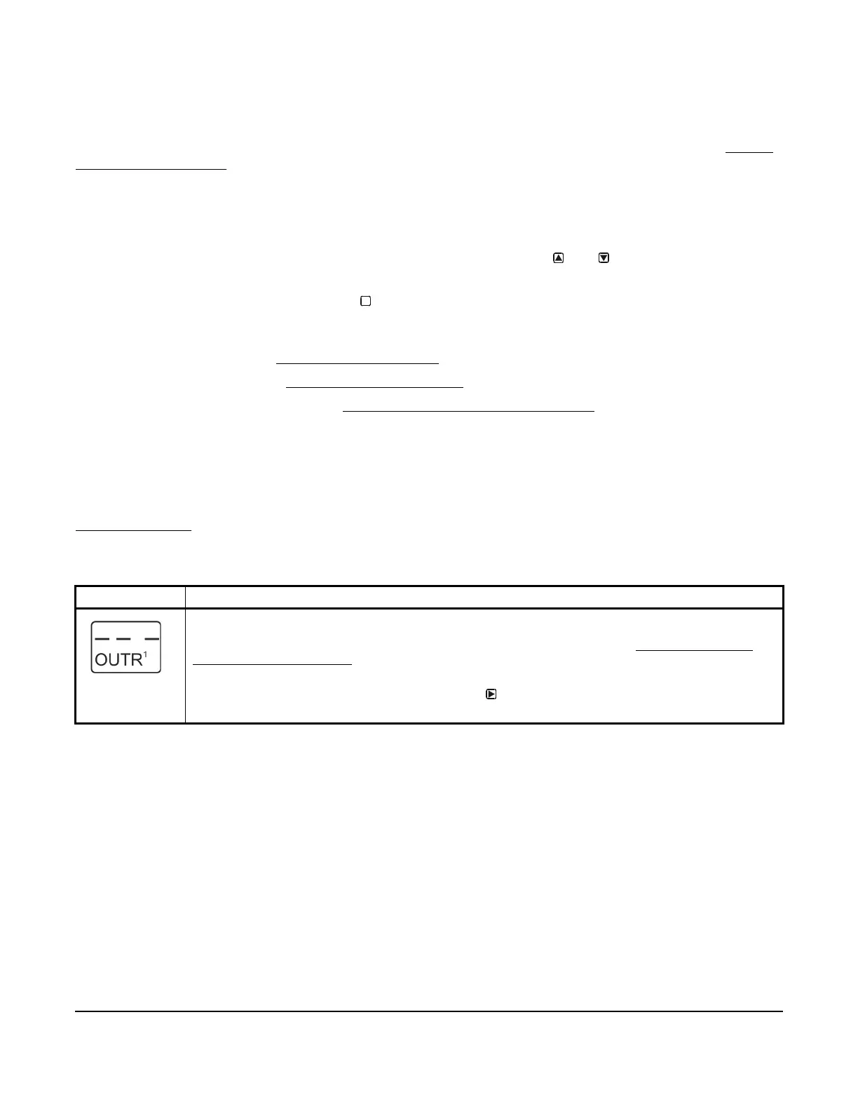
Table 8: System 450 Setup Screen Information and Procedures for Relay Outputs (Part 1 of 4)
LCD Screen Name, Description/Function, User Action, and Example
Relay Output Setup Start Screen: The output numbers and the output type (relay or analog) are
determined by the module types and configuration of your control system’s module assembly and are
automatically assigned when you connect power to the module assembly. (See Setting Up a Control
System in the User Interface on page 5.)
Note: You must set up the control system input sensors before you can set up the outputs.
1. In the Relay Output Setup Start screen, press
to go to the output’s Sensor Selection screen.
The screen example shows a Relay Output Setup Start screen for Output 1.
M
 Loading...

