System 450™ Series Control Modules with Analog Outputs Installation Instructions
24
Setting Up the LCD Backlight Brightness
Beginning with firmware Version 4.00, the LCD backlight brightness can be adjusted in the UI. Table 11 provides
information, procedures, guidelines, and screen examples for setting up the backlight brightness on System 450
control modules. See Figure 6 on page 26 for example menu flow of the backlight set up in Table 11.
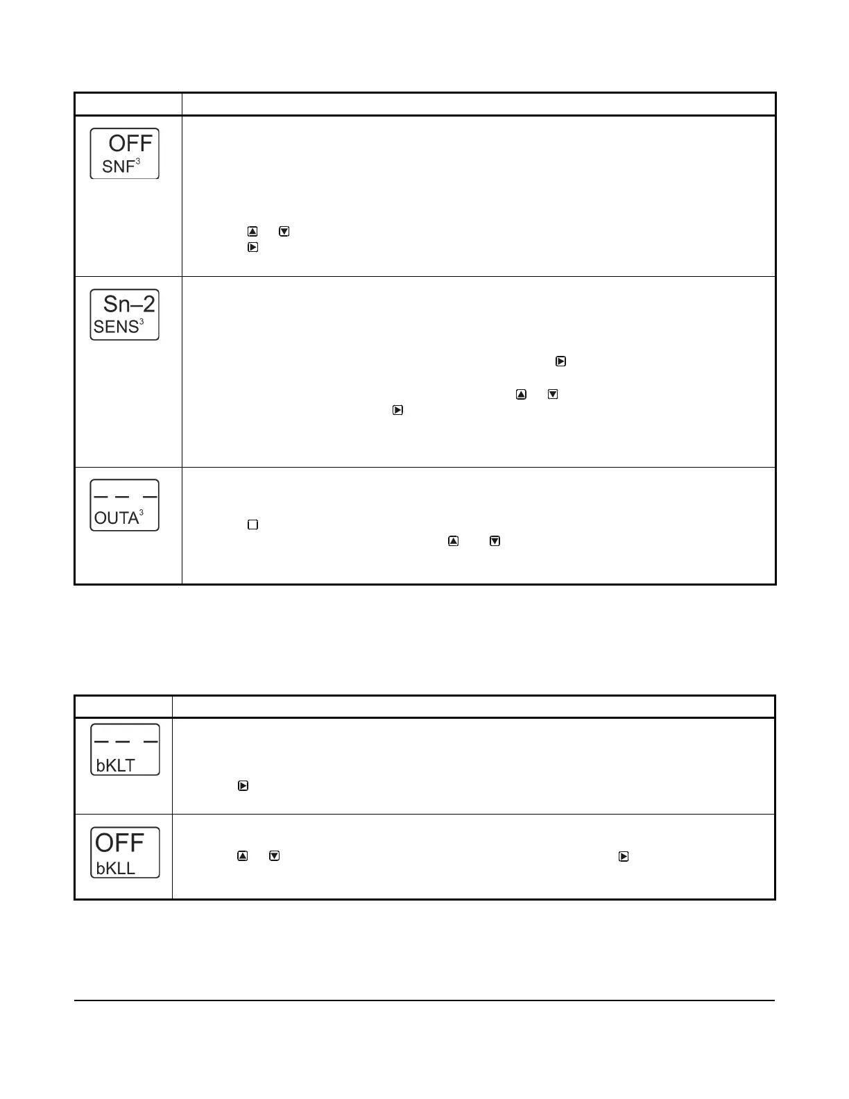
Sensor Failure Mode Selection Screen: Select the output’s mode of operation if a referenced sensor or
sensor wiring fails. For outputs that reference functional sensors HI-2, HI-3, or Sn-d, the failure of any of
the referenced hard-wired sensors results in a functional sensor failure condition. The output operates in
the selected Sensor Failure mode until the failure is remedied. Sensor Failure mode selections for analog
outputs include:
• ON = Output generates the selected OEP signal strength during sensor failure.
• OFF = Output generates the selected OSP signal strength during sensor failure.
10. Press or to select this output’s mode of operation if the sensor or sensor wiring fails.
Press
to save your selection and go to the Edit Sensor Selection screen.
The screen example shows OFF selected as the Sensor Failure mode for Output 3.
Edit Sensor Selection Screen: This screen displays the sensor that this output currently references.
Typically, no action is taken in this screen. But if you need to change the sensor that this output
references, you can select a different sensor for this output in this screen.
Note: If you change the sensor that an output references to a sensor with a different Sensor Type, the
default setup values for the output change, and you must set the output up again.
11. If you are not changing this output’s sensor, simply press to save the current sensor
selection and return to the Analog Output Setup Start screen.
To change the sensor this output references, press or to select the new sensor that this
output references. Then press to save the new sensor selection and return to the Setpoint
Selection screen (SP or dSP). If the new sensor has a different Sensor Type from the previously
referenced sensor, repeat the output setup procedure for this output.
The screen example shows Sn-2 as the selected Sensor for Output 3.
Analog Output Setup Start Screen
After you have set up this analog output, you can go to another Output Setup Start screen or the Backlight
Setup Start screen, or return to the Main screens.
12. Press to scroll through the remaining Output Setup Start screens or the Backlight
Brightness Setup Start screen, or press and simultaneously to return to the System 450
Main screens.
The screen example shows the Analog Output Setup Start screen for Output 3.
Table 11: System 450 Setup Screen Information and Procedures for Backlight Brightness (Part 1 of 2)
LCD Screen Name, Description/Function, User Action, and Example
Backlight Setup Start Screen: The Backlight Brightness level feature allows you to adjust the backlight
intensity. The selected backlight low level value is applied when the control is in idle mode. When you enter
the programming menus to set up the control or press any key, the LCD automatically goes to the selected
backlight high level value.
1. Press to go to the Edit Backlight Low Level screen.
The screen example shows the Backlight Setup Start screen.
Backlight Low Level: The backlight low level defines the brightness of the backlight during regular or idle
mode, when you are not making adjustments to the control.
2. Press or to select the backlight brightness low level value. Press to save your selection
and go to the Edit Backlight High Level screen.
The screen example shows the Backlight low level set to OFF.
Table 10: System 450 Setup Screen Information and Procedures for Analog Output (Part 4 of 4)
LCD Screen Name, Description/Function, User Action, Example
M
 Loading...

