2 V46 Series 2-Way Pressure-Actuated Water-Regulating Valves With Union Fittings Installation Instructions
Table 1: V46 Valve Dimensions, inches (millimeters)
Code
Valve
V46AJ-2C 1/2 in. 3-1/2 (89) 1-13/16 (47) 6-3/8 (162) 3-3/4 (96)
2-5/8 (67)
3/4 in. 3-13/16 (97) 2 (52) 6-13/16 (173) 4-3/16 (106) 2-5/8 (67)
V46AL-2C 1 in. 5-1/8 (130)
2-5/8 (67)
9-11/16 (246) 5-15/16 (151) 3-3/4 (95)
V46AM-2C 1-1/4 in. 5-3/16 (131) 2-5/8 (67) 10-1/8 (260) 6-3/16 (160) 3-15/16 (100)
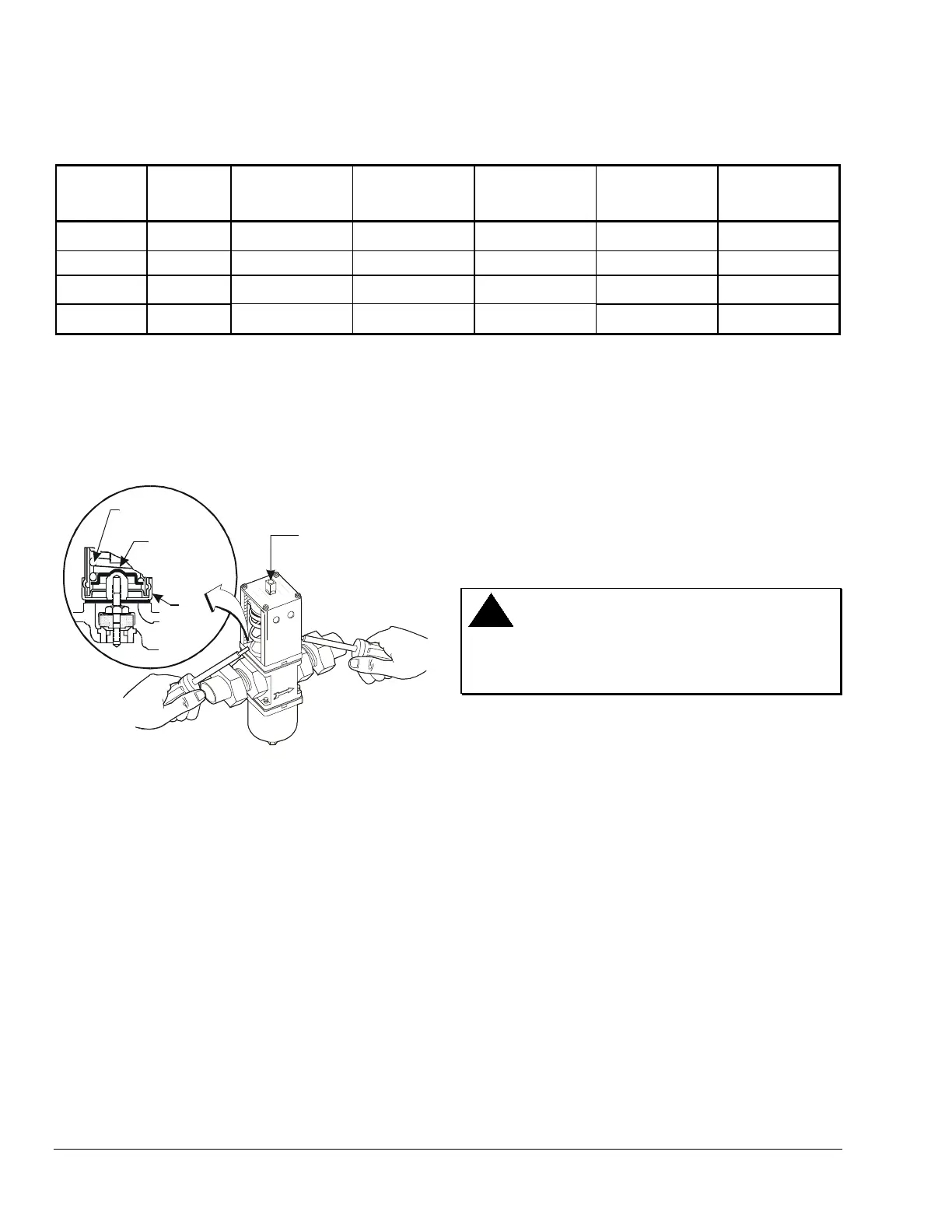
Manually Flushing the Valve
Manually flush the valve and fluid piping before and
after installing, repairing, or replacing a valve to
remove filings, chips, or other foreign matter. Insert
screwdrivers under both sides of the valve spring
guide and lift upwards to flush the valve. See Figure 2.
Manual flushing does not affect valve adjustment.
Range Adjustment
Screw
Range
Spring
Valve Spring
Guide
Top
Retainer
Insert screwdrivers
underneath the valve
spring guide.
Figure 2: Manual Flushing
V46_union_flush.cdr
Location Considerations
Install the valve vertically with the range adjustment
screw on the top and the bellows and pressure
connection line on the bottom to allow drainage of oil
and refrigerant away from the valve bellows.
Do not mount the valve in any position other than
vertical unless specified by the manufacturer of the
equipment on which the valve is installed. Follow the
manufacturer’s installation instructions.
Install the valve on the inlet side of the condenser. If it
is necessary to keep the condenser flooded with
water, install the valve on the outlet side of the
condenser.
If the system is located in an area with high ambient
temperatures, refrigerant head pressures may remain
high enough during off cycles to prevent the valve from
closing completely. In such instances, raise the
opening point of the valve just enough to cause the
valve to close flow to the condenser during
compressor standby periods.
Pressure Connections
WARNING: Risk of Personal Injury.
To avoid possible personal injury, shut off the liquid
supply and relieve the pressure before servicing the
valve.
Connect the refrigerant-side flare connector to the
appropriate high-side pressure tap point. If additional
capillary tubing is necessary, use 1/4-in. tradesize
copper tubing.
Follow the guidelines below when making pressure
connections:
• Use Pressure Tap Points Located on the Top
Side of the Refrigerant Lines
This reduces the possibility of oil, liquids, or
sediment accumulating in the pressure connection
line or valve bellows, which could cause valve
malfunction.
• Avoid Sharp Bends in the Capillary Tubes
Sharp bends can weaken or kink capillary tubes,
which may result in refrigerant leaks or
restrictions.
• Allow for Slack in the Capillary Tubes to
Dampen Vibration
Mechanical vibration can weaken or damage the
capillary tubes.
 Loading...
