9
BIOSHIELD
®
Commercial UV Sterilizer Installation and User's Guide
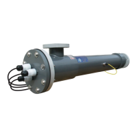
Vertical Installation
Vertical installation requires the bottom port to be
used as the vessel’s inlet and the port closest to
the electrical end to be used as the outlet; allowing
trapped air to escape. If installed on a “by-pass lter
loop” or isolated using valves, an automatic air bleed
system is required. Failure to remove trapped air
can result in rupture or heat damage to the vessel.
4. Isolation Valves are necessary for vessel removal and
chemical cleaning procedure. It is recommended
to install the isolation valves in conjunction with a
separate set of, matching size & type, water port
connections to the inlet/outlet ports of the vessel.
Adding the “double connection” will enable the
UV sterilizer to be removed from the ltration loop
without shutting the total ltration system down.
If this installation arrangement is not possible,
install the unit in a way that chemical cleaners or
freshwater rinse can be drained completely from
the vessel without contaminating the process
water.
5. The UV System (models w/ diameters of 10” and
larger) may have been shipped without their quartz
sleeves installed in the vessel, please install now.
6. The vessel is equipped with a 0.5” female threaded
drain port for installation of the Drain Valve
Assembly. Use thread tape on the threads when
installing the drain valve assembly.
7. The vessel is equipped with various sensor ports
(UV Intensity and Water Temperature Sensors);
additional sensor ports may be included depending
on the model or options purchased with the UV
System. All sensor ports will be labeled on the
vessel based on their respective function. Use
thread tape on the threads to create a reliable seal
with all sensors. Sensors must be threaded into
their respective vessel ports prior to connection
to the power supply enclosure to avoid sensor
damage from cable twisting.
SECTION 3: INSTALLATION