Rev. D 6-26-09 1 P/N 178556
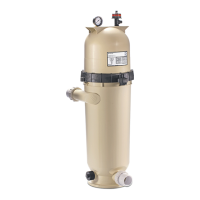
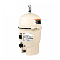
Figure 1.
Pentair Water Pool and Spa, Inc.
1620 Hawkins Ave., Sanford, NC 27330 • (800) 831-7133 • (919) 566-8000
10951 West Los Angeles Ave., Moorpark, CA 93021 • (800) 831-7133 • (805) 553-5000
Visit www.pentairpool.com or www.staritepool.com
Before installing this product, read and follow all warning notices and instructions accompanying this
filter. Failure to follow safety warnings and instructions can result in severe injury, death, or property
damage. Call (800) 831-7133 for additional free copies of these instructions.
WARNING
Important Notice
Attention Installer.
This manual contains important information about the installation, operation and safe
use of this product. This information should be given to the owner/operator of this
equipment.
SECTION I. FILTER INSTALLATION
A. GENERAL INFORMATION
1. The filter should be mounted on a level concrete slab. Position the filter so that the instructions,
warnings and pressure gauge are visible to the operator. Also, position the filter so that the piping
connections, control valve and drain port are convenient and accessible
for servicing and winterizing.
2. Install electrical controls (e.g., on/off switches, timers control systems,
etc.) at least five (5) feet from the filter. This will allow you enough
room to stand clear of the filter during system start up.
3. Provide sufficient clearance around the filter to permit visual verification
that the clamp is properly installed, see Figure 1.
4. Provide sufficient space above the filter to remove the filter lid for
cleaning and servicing. This distance will vary with the model of filter
you are using. See Table 1, for the required vertical clearance.
Clean & Clear
®
Cartridge Filter Owners Manual
IMPORTANT SAFETY INSTRUCTIONS
READ AND FOLLOW ALL INSTRUCTIONS
SAVE THESE INSTRUCTIONS
Table of Contents
SECTION I. FILTER INSTALLATION ............................................................................................... 1
SECTION II. FILTER OPERATION .....................................................................................................2
SECTION III. TROUBLESHOOTING................................................................................................... 6
SECTION IV. TECHNICAL DATA .......................................................................................................7
A. Filter Pressure Loss Chart.......................................................................................... 7
C. Replacement Parts ..................................................................................................... 7
B. Flow Rate Table ......................................................................................................... 7