8
FNS
®
PLUS Vertical Grid D.E. Filter Installation and User’s Guide
Cleaning the Filter Elements (cont.)
4. Reassemble:
a. Starting with the "SMALL GRID" element, place the element on the bottom spreader in the position marked
"SMALL GRID" using the "foot print" pattern as a guide for proper location.
b. Continue positioning the remaining elements onto the spreader in the same manner as the small element.
c. After all elements have been positioned on the bottom spreader, place the plastic template over the element
spouts. This will keep the elements positioned correctly.
d. Position the top manifold over the elements with the stand pipe inlet port pointing in the direction of the small
element. Using moderate force push down on the manifold to seat it on to the elements. Ensure template is
not caught or trapped between manifold and element spouts.
e. Replace the two nuts and the two plastic stand-offs, (if equipped).
f. Replace the completed element assembly into the filter tank.
Cleaning the Internal Air Bleed Tube
It is recommended that the air bleed tube and screen cap be routinely inspected and cleaned. This can easily be done
while the FNS
®
Plus Vertical Grid D.E. Filter lid has been removed for routine maintenance or cleaning.
1. Remove the screen cap from the air bleed tube and rinse both components with water to clean away built-up
debris. Typically, this is all that is needed to properly clean the air bleed assembly.
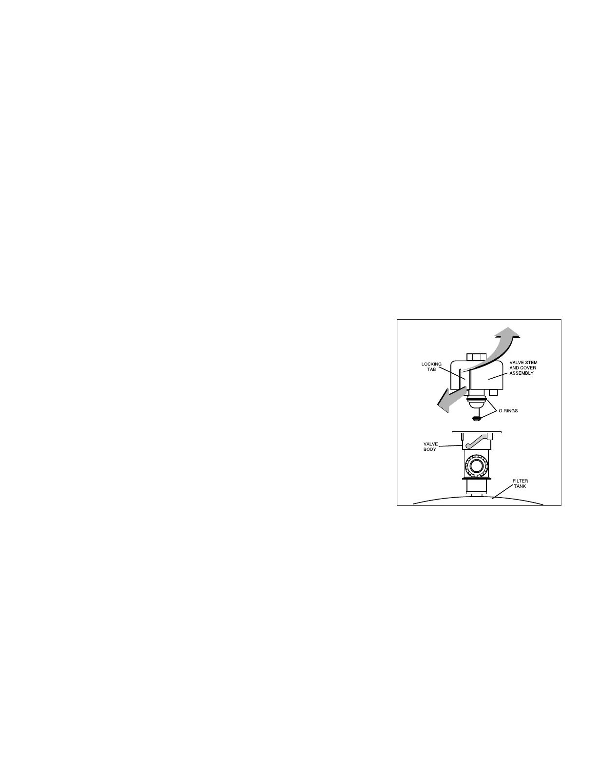
Cleaning the Manual Air Relief Valve
1. Turn the pump and any automatic controls off to ensure that the system
is not inadvertently started during servicing.
2. Open the High Flow™ Manual Air Relief Valve until it snaps into the full
open position and wait until all pressure is released from the system.
3. With the manual air relief valve attached to the filter tank, pull out the
locking tabs and remove the valve stem and cover assembly with a
counter-clockwise and lifting motion. See Figure 4.
4. Clean debris from the valve stem and body. Insert a 5/16” drill bit
through the valve body to ensure the filter tank’s air passage is open.
5. Be sure the O-rings are in good condition, properly positioned, and
lubricated with a silicone base lubricant.
6. Reinstall the valve stem and cover assembly with a downward and
clockwise motion until it snaps into position.
Figure 4