2
FNS
®
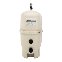
PLUS Vertical Grid D.E. Filter Installation and User’s Guide
General Installation Information
1. Your FNS
®
Plus Vertical Grid D.E. Filter requires one of the following accessories which must be purchased
separately.:
a. Push-Pull valve
b. Multiport valve
c. Bulkhead union set
2. Make all plumbing connections in accordance with local plumbing and building codes. Filter plumbing connections
are provided with an O-ring seal. To avoid damage to the O-rings, use only a silicone base lubricant on the
O-rings. Do not use pipe joint compound, glue or solvent on the bulkhead connections.
3. Remove the plug from the top of the filter lid and install the pressure gauge before use.
4. The maximum working pressure of this filter is 50 psi. Never subject this filter to pressure in excess of this amount
- even when conducting hydrostatic pressure tests.
When performing hydrostatic pressure tests or when testing for external leaks of the completed filtration and
plumbing system, ensure that the maximum pressure that the filtration system will be subjected to DOES
NOT EXCEED THE MAXIMUM WORKING PRESSURE OF ANY OF THE COMPONENTS CONTAINED
WITHIN THE SYSTEM. In most cases, the maximum working pressure will be stated on each component of
the system.
If doubt exists as to the pressure to which the system will be subjected, install an ASME approved automatic
Pressure Relief or Pressure Regulator in the circulation system for the lowest working pressure of any of the
components in the system.
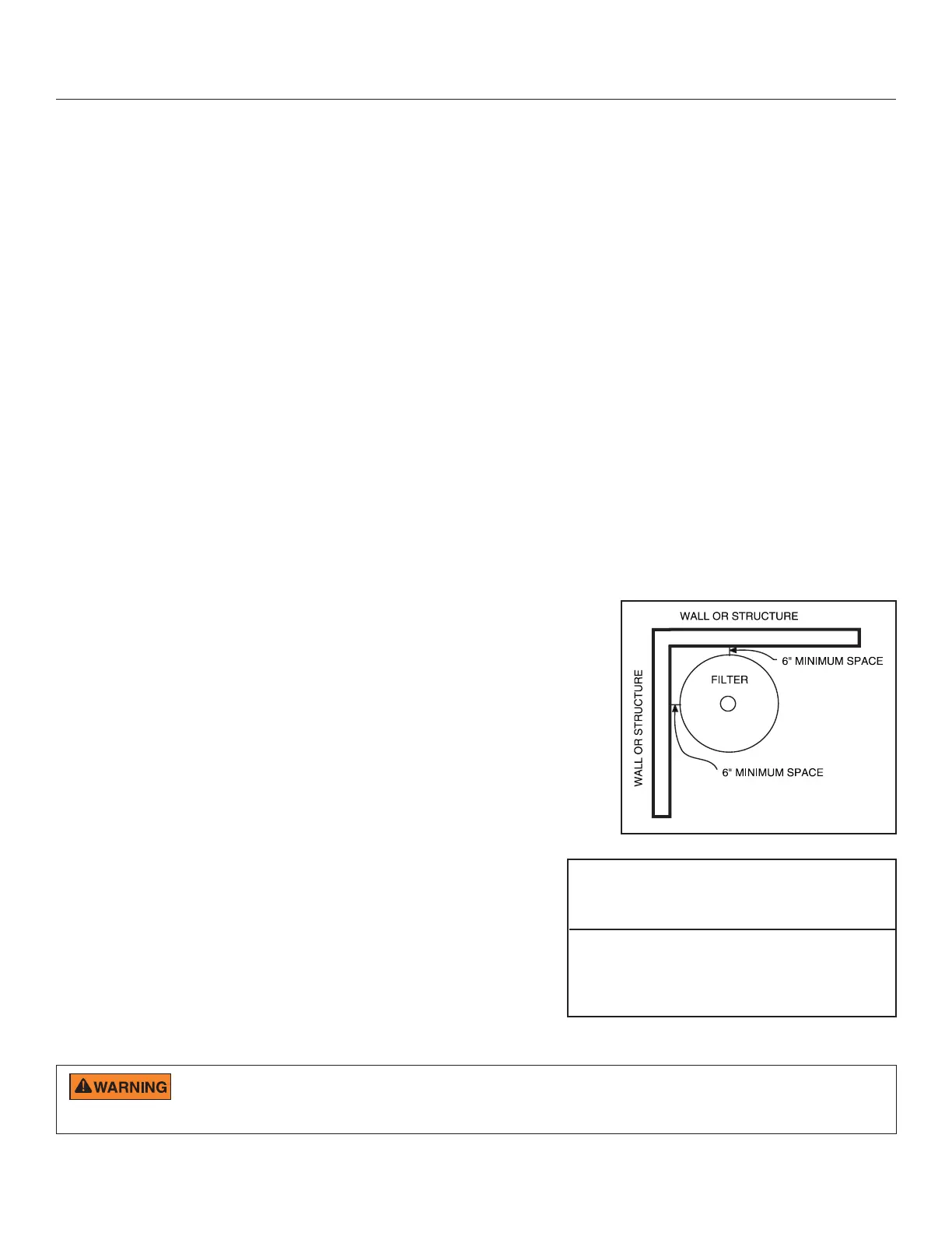
Filter Location
1. Mount the filter on a level concrete slab. Position the filter so that
instructions, warnings and the pressure gauge are visible to the
operator.
2. Position the filter so that the piping connections, control valve and
drain port are convenient and accessible for servicing and winterizing.
3. Install electrical controls (e.g., on/off switches, timers, control
systems, etc.) at least five (5) feet from the filter. This will allow you
enough room to stand clear of the filter during system start up.
4. Allow sufficient clearance around the filter to permit visual verification
that the clamp is properly installed around the tank flanges, see
Figure 1.
Note: Tap the clamp with a mallet or similar tool to ensure uniform
loading during clamp tightening.
5. Allow sufficient space above the filter to remove the filter lid for
cleaning and servicing. This distance will vary with the model
of filter you are using. See Table 1 for the required vertical
clearance.
6. Position the filter to safely direct water drainage. Rotate the
High Flow™ Manual Air Relief Valve to safely direct purged air
or water. Water discharged from an improperly positioned filter
or valve can create an electrical hazard as well as damage
property.
Table 1
Vertical
Model Size Clearance Req. NSF
FNSP 24 24 sq. ft. 48 in. yes
FNSP 36 36 sq. ft. 62 in. yes
FNSP 48 48 sq. ft. 74 in. yes
FNSP 60 60 sq. ft. 86 in. yes
Figure 1
Risk of electrical shock or electrocution. Position the filter and manual air relief valve to safely direct water
drainage and purged air or water. Water discharged from an improperly positioned filter or valve can create an
electrical hazard that can cause severe personal injury as well as damage property.
INSTALLATION