General Information 3
GENERAL INFORMATION
All tanks are factory pre-charged with air. When
installing tank, adjust pre-charge to 2 PSI below
pump cut-in pressure setting. To do this, bleed or
add air through valve on top of tank.
NOTICE: Transport and install tank in vertical
position ONLY!
NOTICE: Always set pre-charge with NO WATER
in tank.
Check pressure frequently with an accurate tire
pressure gauge until correct pressure has been
reached. For correct pre-charge pressure settings,
see Chart 1, below.
CHART I
Tank Precharge Settings for use with PENTEK
INTELLIDRIVE Variable Frequency Drives
Set the pressure tank’s pre-charge to 70% of the
system operating pressure. When using an external
set point as well as an internal set point, pre-
charge the tank to 70% of the lower set point of
the two. Some applications may require a different
percentage when figuring the set point. Refer to
your
PENTEK INTELLIDRIVE operator’s manual for
additional information.
NOTICE: Replace and tighten air valve cap if it is
re moved for any reason. Failure to replace air cap
may allow loss of air pressure and eventually lead
to tank waterlogging and water cell failure.
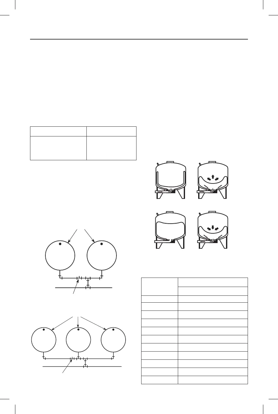
Pre-charged storage tanks can be connected
together to increase the supply of usable water
(drawdown). Two tanks of the same size will
double the supply and three tanks will triple the
supply. See Figures No. 1A and 1B for typical
installations of this kind.
OPERATING CYCLE
1. Tank nearly empty – air expands filling area
above vinyl water cell (Fig. 2A).
2. Water begins to enter tank – air is compressed
above water cell as it fills with water (Fig. 2B).
3. Pump-up cycle completed – air now
compressed to cut off setting of pressure switch
(Fig. 2C).
Pressure Switch Setting Tank Precharge (PSI)
20-40 PSI 18
30-50 PSI 28
40-60 PSI 38
Pressure Switch Setting (PSI)
Model 20-40 30-50 40-60
PS6-S02 2.2 1.8 1.6
PS6H-S05 2.2 1.8 1.6
PS19S-T02 6.9 5.8 5.0
PS19T-T02 6.9 5.8 5.0
PS19H-S00 6.9 5.8 5.0
PS32-T03 11.6 9.8 8.5
PS35-T05 12.7 10.7 9.3
PS50-T50 18.3 15.5 13.4
PS62-T51 21.4 18.3 16.0
PS85-T52 30.0 26.0 22.0
PS119-TR50 41.3 35.4 31.0
From
Well
To
Service
Tanks
Pressure Switch
Figure 1A
From
Well
To
Tanks
Pressure Switch
Figure 1B
Figure 2
WATER
WATER
WATER
CHART II – Water Yield Per Pump Cycle
(drawdown) in Gallons