EasyManua.ls Logo

Pentair T40-F - User Manual

Pentair T40-F
4 pages
Print Icon
To Next Page IconTo Next Page
Loading...
Installation Instructions
Prior to installation, check local building codes for exceptions to these instructions.
1. Install leveler bucket so top of bucket is flush with bond beam of pool (See Fig. A). Ring and
Lid then should be installed flush with deck. Use rebar mounting flanges provided on bucket
to insure and aid in keeping bucket level during concrete pour.
2. Install 1½" equalizer pipe. IMPORTANT: Equalizer pipe must be straight, as shown in Figure
A. The use of any 45° or 90° pipe could cause air lock and void warranty. Use only PVC to ABS
transition cement for this application.
3. Connect 3/4" fresh water supply pipe to side leveler bucket. (See Fig. A). Special Note: Please
allow adequate cure time as per cement manufacturer before applying pressure.
4. You can pressure test auto-fill with supplied fitting P/N 210067. (See Fig. D). CAUTION: Do not
over tighten.
5. Remove test plug and flush supply line for approximately 60 seconds or until all debris has
cleared.
6. Connect 3/4" overflow pipe in port (See Fig. A), using a PVC to ABS transition cement.
7. Install valve assembly, Fluidmaster
®
Valve with PTFE thread seal tape. IMPORTANT: Do not
use liquid or paste sealers. Pentair Water Pool and Spa, Inc. does not cover warranty if
damaged because of over tightening or cross threading.
8. To adjust float height of Fluidmaster
®
valve, lightly press down the top of fill valve with one
hand, while turning clockwise or counter-clockwise to adjust valve. Continue turning until
water level is achieved. (See Figure E).
Pentair Water Pool and Spa, Inc.
1620 Hawkins Ave., Sanford, NC 27330 • (800) 831-7133 • (919) 566-8000
10951 West Los Angeles Ave., Moorpark, CA 93021 • (800) 831-7133 • (805) 553-5000
www.pentairpool.com or www.staritepool.com
P/N YYLEVF Rev. C 12/2015
MODEL T40-F
AUTOMATIC POOL FILLER
1
Question and Answer IconNeed help?

Do you have a question about the Pentair T40-F and is the answer not in the manual?

Summary

Automatic Pool Filler Installation

Leveler Bucket and Pipe Connections

Install leveler bucket, equalizer pipe, water supply, and overflow pipe correctly.

Valve Assembly and Float Adjustment

Install Fluidmaster® valve assembly and adjust float height for proper water level.

System Testing and Flushing Procedures

Perform pressure tests and flush supply lines to ensure proper function and clear debris.

Installation Diagrams and Components

Figure A: Overall System Diagram

Illustrates the placement and connection of components relative to the pool deck and bond beam.

Figure B: Deck Ring and Flange Detail

Shows the adjustable ring for the deck and the rebar mounting flange for the bucket.

Component Dimensions and Specifications

Figure C: Filler Bucket Dimensions

Provides detailed measurements for the filler bucket, including slip fit sizes and minimum clearances.

Parts and Adjustment Illustrations

Figure D: Test Plug Identification

Identifies the supplied test plug (P/N 210067) and emphasizes not to overtighten it.

Figure E: Fluidmaster Valve Adjustment

Demonstrates how to adjust the Fluidmaster® valve height and clear debris from the screen.

Overview

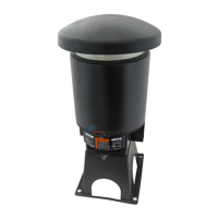
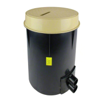
The Pentair Automatic Pool Filler, Model T40-F, is a device designed to maintain a consistent water level in a pool. It operates by automatically adding fresh water when the pool's water level drops below a set point, ensuring the pool remains at its optimal operating level.

Function Description:

The core function of the T40-F is to monitor and regulate the pool's water level. It consists of a leveler bucket, an equalizer pipe, a fresh water supply connection, an overflow pipe, and a valve assembly with a float. When the pool's water level drops, the float in the valve assembly lowers, opening the valve and allowing fresh water to enter the leveler bucket. This water then flows into the pool via the equalizer pipe until the desired water level is restored, at which point the float rises and closes the valve. The system is designed to prevent air lock, which could impede its function, by requiring a straight equalizer pipe. An overflow pipe is also integrated to prevent overfilling in case of a malfunction or excessive water input.

Important Technical Specifications:

  • Equalizer Pipe: Requires a 1½" equalizer pipe. Crucially, this pipe must be straight to prevent air lock and maintain warranty validity. The use of 45° or 90° pipes is explicitly prohibited for this connection.
  • Fresh Water Supply: Connects via a ¾" fresh water supply pipe to the side of the leveler bucket.
  • Overflow Pipe: Connects via a ¾" overflow pipe.
  • Materials: PVC to ABS transition cement is specified for connecting the equalizer and overflow pipes.
  • Dimensions (Referencing Figure C):
    • Overall Diameter (Top): 7.3" DIA.
    • Overall Diameter (Body): 8.15" DIA.
    • Height from top of bucket to equalizer line: 13.5" (+1.5", -0")
    • Height from top of bucket to fresh water supply: 3.8" (+1.5", -0")
    • Minimum height from top of bucket to overflow: 2.6"
    • Total minimum height: 16.7"
    • Distance from center to overflow (top view): 1¾"
  • Valve Assembly: Utilizes a Fluidmaster® Valve.
  • Test Plug: Supplied with P/N 210067 with an O-ring (no through hole) for pressure testing.

Usage Features:

  • Installation:
    • The leveler bucket should be installed so its top is flush with the pool's bond beam. The ring and lid should then be flush with the deck. Rebar mounting flanges are provided on the bucket to aid in leveling during concrete pouring.
    • The top of the automatic filler bucket should be flush to 1" above the bond beam maximum (as per Figure A).
    • The cover ring offers limited vertical adjustment. Perforated knock-outs on the box and cardboard can be used to prepare for deck installation.
  • Pressure Testing: The system can be pressure tested using the supplied fitting P/N 210067. Users are cautioned not to overtighten this fitting.
  • Water Level Adjustment: The Fluidmaster® valve's float height can be adjusted to achieve the desired pool water level. This is done by lightly pressing down on the top of the fill valve with one hand and turning it clockwise or counter-clockwise (as shown in Figure E). Alternatively, the valve height can be adjusted by screwing the valve up or down.
  • Sealant Requirements: PTFE thread seal tape is specified for the valve assembly. Liquid or paste sealers are explicitly prohibited, and their use will void the warranty if damage occurs due to overtightening or cross-threading.

Maintenance Features:

  • Flushing Supply Line: Before connecting the valve assembly, the supply line should be flushed for approximately 60 seconds, or until all debris has cleared, to prevent contamination of the system.
  • Debris Screen: The valve assembly includes a debris screen (shown in Figure E). To clear sand and debris from the supply line, this screen can be removed, cleaned, and then reinstalled along with the valve. This feature helps prevent clogging and ensures the continuous proper operation of the valve.
  • Warranty: The manufacturer emphasizes that damage due to overtightening or cross-threading, especially when using prohibited sealants, will void the warranty. This highlights the importance of careful installation and adherence to instructions.

Pentair T40-F Specifications

General IconGeneral
BrandPentair
ModelT40-F
CategoryLighting Equipment
LanguageEnglish

Related product manuals