GB - 15
!
!
!
!
!
!
!
!
!
!
Before assembly and initial operation of the device, check that the
deliveryiscompleteandundamaged.
The device must only be repaired by authorized and skilled specialists.
Failuretoobserve this instructionrisks damageresulting fromimproper
useandlossofthewarranty.
Use theindoor unitat anoperating temperature of+5° C- + 40°C.
Higherorlowertemperaturescanadverselyaffectoperation.
If required, a standard 12 V DC door release can be connected to the
system. The door release must be operated with 12 V DC and have a
max.currentconsumptionof1A.
The mains cable for this door intercom must only be replaced by the
manufacturerorbyanauthorizedspecialist.
Install the outdoor unit so that it is protected from external influences
(e.g.rainorsnow).
Makesurethat thedeviceis notexposedto strongstatic, electricor high
frequency fields (static discharge, mobile radiotelephone, radio sets,
microwaves). These may have an adverse effect on the function of the
doorintercom.
The receiver on the indoor unit is for speaking into and listening during
communication withtheoutdoor unit.The doorreleasebutton [3]is usedto
switch on a standard 12 V DC doorrelease (not included). The latter can be
connectedwithatwin-corecable(withcodedcores,notincluded).
The bell button [16] activates the bell on the indoor unit. The microphone
[18] is for speaking and the loudspeaker [15] for listening during
communicationwiththeindoorunit.
The connection between the outdoor unit and the indoor unit can be made
withthetwin-core cable(withcodedcores). Thelengthofthe cablecanbeup
toapprox.200m(seeTechnicaldata).
whenmaking theinstallationposition,disconnectthe indoor
unitfromthemainspowersupply.
Decide on a suitable position for installation of the indoor unit, the
outdoor unit and optionally for the door release (see manufacturer‘s
instructions intheoperating manual forthedoor release).Please make
sure that there is a mains socket for the mains power supply at a max.
distanceof1,5mfromtheindoorunit.
You may install the indoor unit either on an even surface (shelf or
cabinet)oronawall.Makesurethatthecableisasuitablelength.
Lead the twin-core cable from the installation site of the indoor unit to
theinstallationsiteoftheoutdoorunit.
Initialoperation
Connection
Function
Choosingthe installationpositions
Danger!
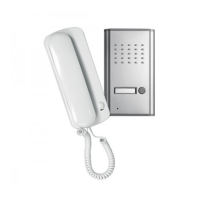
Handset
Outdoorunit
!
!
!
!
!
!
!
!
!
!
!
!
!
!
!
!
Install the cable so that it is protected from external influences, e.g.
concealed,ifnecessaryuseastandardcableduct.
Make surethatyou haveapprox. 0cm ofcable available forconnection
directlyattheconnectingareasfortheindoorunitandoutdoorunit.
Carefully remove the insulation from the end of the cable cores to a
length of approx. 8 mm. The bared cores can be connected to the
terminalScrews.
make sure that the cable is connected correctly. The cable
must be connected according to the core coding. If the cores are connected
incorrectly,thedoorintercomcannotworkproperly.
Removethemountingplate[10]fromtheindoorunit.
Guidethe firstcable (anda secondif connectinga doorrelease) through
thecentreofthemountingplateandthecableopening[12].
Connect the first core(e.g.black)of thefirstcable(from theindoorunit
totheoutdoorunit)toterminalscrew1[6].
Connect the second core (e.g. white) of the first cable (from the indoor
unittotheoutdoorunit)toterminalscrew2[7].
Pushtheplugofthereceivercable [4]completely intothe receivercable
socketonthehandset(atthebottominthecentreofthehandset).
Carry out the installation and connection preparations for the door
release according to the manufacturer‘s instructions (operating
manual).
Connect the first core (e.g. black) of the second cable (from the door
release to the indoor unit to terminal screw S1 [8] and the
correspondingterminalscrewofthedoorrelease.
Connect the second core (e.g.white)ofthe second cable (fromthedoor
release to the indoor unit) to terminal screw S2 [9] and the
correspondingterminalscrewofthedoorrelease.
Remove the retaining screw 1 [23] and take the housing [14] off the
flushmountbox[19].
Guidethefirstcablethroughthecableopening[21].
Connect the first core(e.g.black)of thefirstcable(from theindoorunit
totheoutdoorunit)toterminalscrew1[24].
Connect the second core (e.g. white) of the first cable (from the indoor
unittotheoutdoorunit)toterminalscrew2[25].
With modell DP 602 connect the second core (eg. white) from the
secondindoorunittoterminalscrew3[26].
Figure E/F shows connection of all components (optionally with door
release).
Indoorunit(seeFig.B)
Receiver
Optionalforconnectionofa12VDCdoorrelease:
Outdoorunit
Caution!
 Loading...