11
Door Interrupt System with FYQLA1-140R-3 Logic Amplier
Indicators
The FYQLA1-140R-3 has indicators on front of the device for the following
functions:
• State of the connected input switches
▸ Two indicators per switch input (channel A & channel B)
▸ Indicator is illuminated (on) when the switch state is open
• Relay output status
▸ Two indicators available, one per relay state:
Red indicator illuminated when de-energized
Green indicator illuminated when energized
• Fault Indicator
▸ Fault indicator ashes under the following conditions:
Input switch sequence error (channel A and channel B timing)
▸ Output relay contact monitor fault
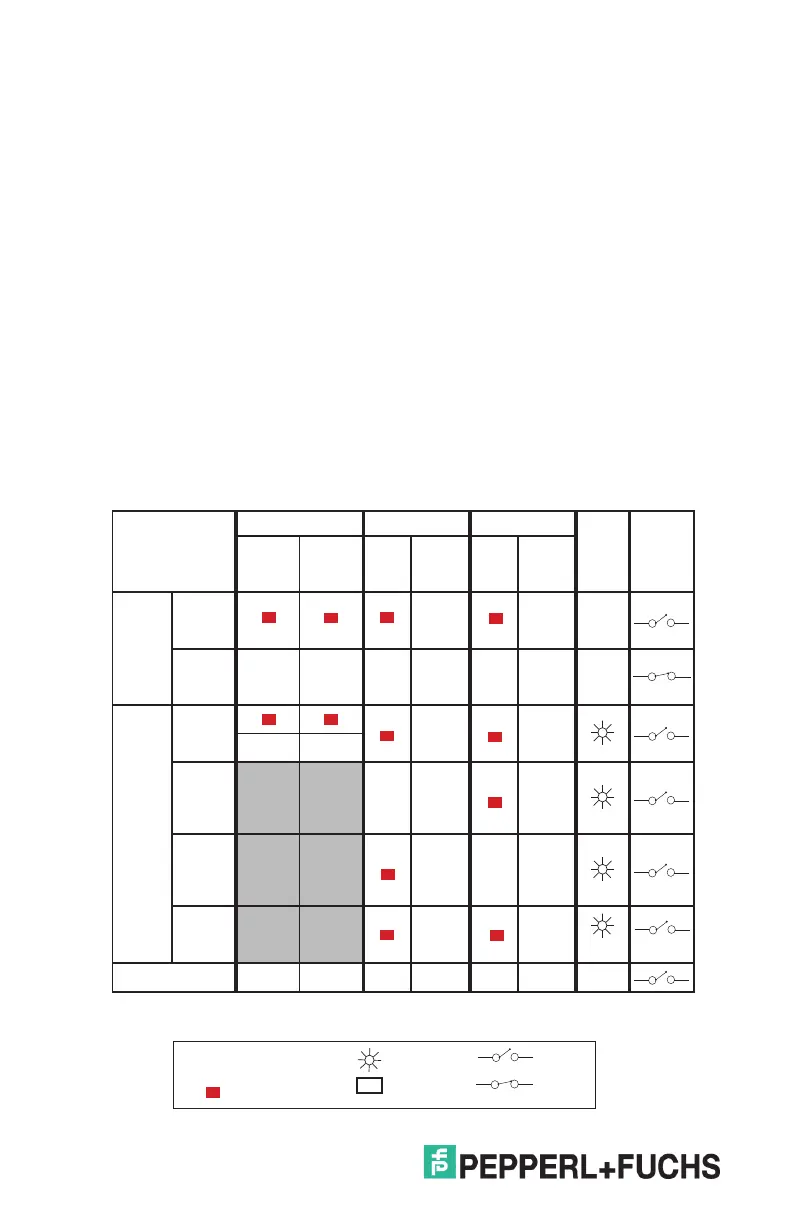
Indicator status table
Condition
Switch Status Relay 1 Status Relay 2 Status
Red
Fault
LEDs
SR1
Contact
Status
Red
Channel
1 LED
Red
Channel
2 LED
Red
Open
LED
Green
Closed
LED
Red
Open
LED
Green
Closed
LED
Normal
Operation
Door
Sensor
Open
Door
Sensor
Closed
p p
Faults
Door
Sensor
Fault
1
Relay 1
Welded
Contact
Fault
2
p
Relay 2
Welded
Contact
Fault
2
p
Internal
Relay
Fault
2
Power O
1) Indicator status changes to fault 1-2 seconds after input sequence fault is detected
2) Fault may require the next operational cycle to start before fault is indicated
Red
BLINKING
OFF
OPEN
CLOSED
p
Green LED ON
Red LED ON
 Loading...