20
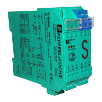
Door Interrupt System with FYQLA1-140R-3 Logic Amplier
Fault diagnosis
If fault LED ashes and no sensor alignment problem can be found:
• Turn o power
• Unwire sensors from input terminals
• Power up unit
•
If fault LED begins to ash repeatedly after 2-3 seconds, the system needs to be
replaced. If the fault LEDs do not begin to ash:
• Remove power, then wire one sensor (R,W,B,O) connection at a time. Apply
power, waiting 2-3 seconds. Repeat sequence with all sensors until fault
LED begins to ash. This will be the sensor/actuator that is generating
the fault condition. Reevaluate alignment and terminal connections. If no
problem is found, replace the sensor and/or actuator in question
Approvals
UL508
Input specications
FYQLA1-140R-3 120 VAC ± 15% <0.25A @ 45 to 65 Hz
Input devices (6) dedicated noncontact hall eect door
sensors (50FY41 series)
Switch voltage input 12 VDC (2 channel, sink/source)
Typical response time 20 ms (switch open to contact open)
Power up time 3 s
Output specications
Contact material AgCuNi + 0.2 um Au
Continuous current 5 mA to 5 A (N.O. contact)
Relay type 1 relay output, force guided connection,
normally open contacts
Inrush current (max) 30 A for 20 ms
Maximum switching
characteristics
(Determined acc. to
EN60947-4-1/EN60947-5-1)
External fusing should be added
to protect the application and unit
from unforseen circumstances
AC-1: 250 V/5 A (100,000 cycles)
AC-15: 230 V/3 A (150,000 cycles)
DC-1: 24 V/5 A (100,000 cycles)
DC-13: 24 V/1 A /0.1 Hz (100,000 cycles)
Product specications
 Loading...