2019-10
22
Functional Safety KFD2-UT2-(Ex)*(-1)
Operation
5.2.4 Potentiometer Input
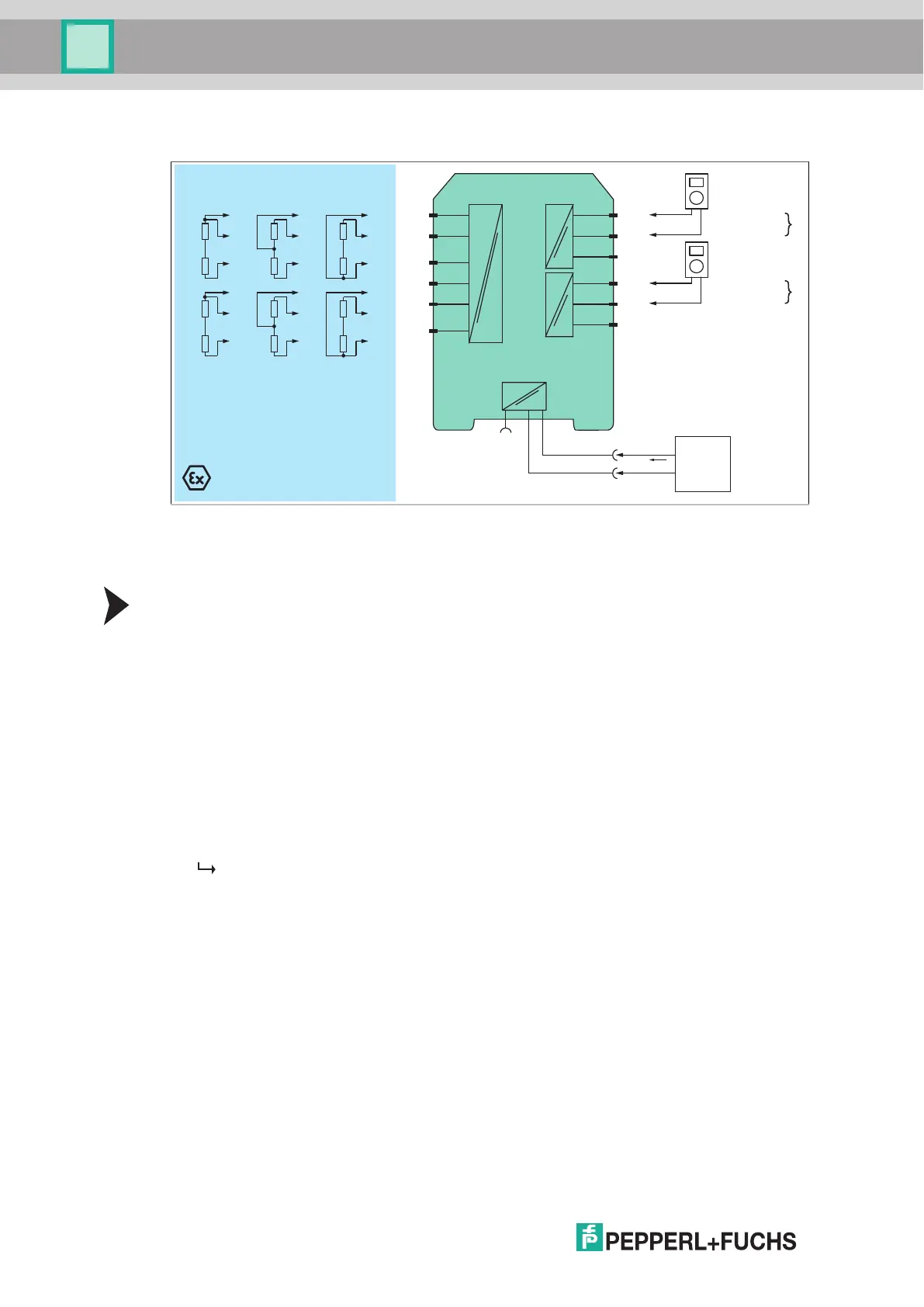
Figure 5.4 Proof test set-up for KFD2-UT2-(Ex)*(-1) with potentiometer input
Usage in Zone 0, 1, 2/Div. 1, 2 only for KFD2-UT2-Ex1(-1) and KFD2-UT2-Ex2(-1)
1-channel versions KFD2-UT2-1(-1) and KFD2-UT2-Ex1(-1) have only one channel.
Proof Test Procedure for Output as Current Source
The resistor values which are used to simulate the potentiometer shall be chosen
so that they represent the full scale value of the potentiometer when connected in series.
The individual resistors shall be of the same resistance value and have an accuracy of 1 %.
1. Connect the series resistors for 0 %, 50 % and 100 % of the potentiometer value
to the terminals 2 and 3 (channel I) and 5 and 6 (channel II), see figure.
2. Connect the one-shot input to the terminals 1 (channel I) and 4 (channel II)
to the junction of the two simulation resistors.
3. Connect the digital multimeter to the terminals 7 and 8 (channel I)
and 10 and 11 (channel II).
4. Set the simulation resistor to 0 %, 50 % and 100 % of the potentiometer value.
5. Measure the output current.
The proof test is passed if the output values are within 2 % of the output span.
1
This means:
– for 0 % of the potentiometer value: 3.7 mA to 4.3 mA
– for 50 % of the potentiometer value: 11.7 mA to 12.3 mA
– for 100 % of the potentiometer value: 19.7 mA to 20.3 mA
6. Remove the series resistors.
7. Set the device back to the original settings after the test.
Zone 0, 1, 2
Div. 1, 2
Zone 2
Div. 2
KFD2-UT2-Ex2
0 % 50 % 100 %
2
3
1
5
6
4
7
9-
8+
10
12-
11+
Fault
I supply
Multimeter
(mA)
Multimeter
(mA)
I
II
Supply +
Supply -
24 V DC
Power
supply
Supply
Bus
1
Additionally the loop diagnosis shall be tested to prove that the fault signaling via the current output is working
correctly. The output current in the event of a failure depends on the device configuration. Please record
this configuration and the resulting expected fault signaling current in the test report. Example: if downscale
is configured, 2.0 mA ±1 % must be measured in the event of a failure. The red LED must be flashing.