www.pepperl-fuchs.com
Subject to modication • Pepperl+Fuchs
EDM 455622b • Release 08/2020
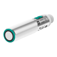
Inbetriebnahmeanleitung für Ultraschallsensor-Serie UC-18GS mit 1 Schaltausgang und 1 Analogausgang
Commissioning instruction for ultrasonic sensor series UC-18GS with 1 switching output and 1 analog output
Beschreibung der Sensorfunktion
Produktinformationen
Weitere Informationen zum Produkt wie Technische Daten, Ansprechkurven, Maßzeichnungen etc. nden Sie auf der zugehörigen Produktseite
des Sensors auf www.pepperl-fuchs.de.
Einstellmöglichkeiten
Der Sensor ist mit 1 Schaltausgang mit 2 programmierbaren Schaltpunkten und 1 Analogausgang mit 2 programmierbaren Grenzen ausge-
stattet. Die Programmierung der Schaltpunkte/Grenzen, der Ausgangsmodi, des Ausgangsverhaltens sowie der Schallkeulenbreite kann auf 2
verschiedene Arten vorgenommen werden:
• Mittels Programmiertasten des Sensors
• Über die IO-Link-Schnittstelle des Sensors. Diese Methode erfordert einen IO-Link Master (z.B. IO-Link-Master02-USB) und die zugehörige
Software. Sie nden den Link zum Download auf www.pepperl-fuchs.de auf der Produktseite des Sensors.
Die Programmierung mit den Programmiertasten ist im Folgenden beschrieben. Für die Programmierung über die IO-Link-Schnittstelle des
Sensors lesen Sie bitte das Handbuch, das Sie ebenfalls auf der Produktseite des Sensors nden. Die Programmierung der Schaltpunkte und
der Sensorbetriebsarten erfolgt völlig unabhängig voneinander, ohne gegenseitige Beeinussung.
Hinweis
• Die Möglichkeit der Programmierung besteht in den ersten 5 Minuten nach dem Einschalten. Sie verlängert sich während des Program-
miervorgangs. Nach 5 Minuten ohne Programmiertätigkeit wird der Sensor verriegelt. Danach ist kein Programmieren mehr möglich, bis der
Sensor aus- und eingeschaltet wird.
• Bei aktiver Kommunikation über die IO-Link-Schnittstelle des Sensors ist die Programmierung über die Progammiertasten nicht möglich.
• Es besteht jederzeit die Möglichkeit den Programmiervorgang abzubrechen, ohne Änderungen der Sensoreinstellung. Drücken Sie dazu die
Programmiertaste für 10 s.
• Die Programmierung über die Programmiertasten kann im Alleinbetrieb eines Sensors oder auch im synchronisierten Sensorverbund
mehrerer Sensoren erfolgen (nur bei automatischem Gleichtaktbetrieb und Multiplexbetrieb). Bei Programmierung im synchronisierten
Sensorverbund startet die Programmierroutine ggf. zeitlich verzögert, abhängig davon wann der betreende Sensor an der Reihe ist. Für
die Dauer des Programmiervorgangs gehen die anderen Sensoren im Sensorverbund in den Standby (grüne LED blinkt). Danach läuft der
Synchronisationsbetrieb normal weiter.
1
5
2
3
4
L+
I/U
SYNC
C/Q
L-
1
5
2
3
4
L+
I/U
SYNC
C/Q
L-
Programmierung des Schaltausgangs über Programmiertaste T1 und des Analogausgang über
Programmiertaste T2
Hinweis
Programmiertaste T1 ist für den Schaltausgang und T2 ist für den Analogausgang. Die Schallkeulenbreite wird jedoch generell für den Sensor
eingestellt, entweder über Programmiertaste T1 oder T2.
Die nachfolgend dargestellten Programmierabläufe müssen Sie jeweils separat pro Ausgang durchführen. Zur Vereinfachung wird die Program-
miertaste im Folgenden T genannt.
Wenn das Objekt während des Programmiervorgangs korrekt erkannt wird, blinkt die gelbe LED langsam. Wenn kein Objekt erkannt wird, blinkt
die gelbe LED mit einer höheren Frequenz. Eine blinkende rote LED während oder bei Abschluss des Programmiervorgangs signalisiert eine
unsichere Objekterkennung. Korrigieren Sie in diesem Fall während des Programmiervorgangs die Ausrichtung des Objekts, bis die gelbe LED
blinkt. Nur so werden die Einstellungen in den Speicher des Sensors übernommen.
Programmierung von Schaltpunkt 1(SP1) des Schaltausgangs über T1
1. Positionieren Sie das Objekt am Ort des gewünschten Schaltpunktes.
2. Drücken Sie die Programmiertaste T für 2 s (gelbe LED blinkt).
3. Drücken Sie die Programmiertaste T kurz (grüne LED blinkt 3x zur Bestätigung). Der Sensor kehrt in den Normalbetrieb zurück.
Programmierung von Schaltpunkt 2 (SP2) des Schaltausgangs über T1
1. Positionieren Sie das Objekt am Ort des gewünschten Schaltpunktes.
2. Drücken Sie die Programmiertaste T für 2 s (gelbe LED blinkt).
3. Drücken Sie die Programmiertaste T für 2 s (grüne LED blinkt 3x zur Bestätigung). Der Sensor kehrt in den Normalbetrieb zurück.
Programmierung der nahen Grenze (SP1) des Analogausgangs über T2
1. Positionieren Sie das Objekt am Ort der gewünschten nahen Grenze.
2. Drücken Sie die Programmiertaste T für 2 s (gelbe LED blinkt).
3. Drücken Sie die Programmiertaste T kurz (grüne LED blinkt 3x zur Bestätigung). Der Sensor kehrt in den Normalbetrieb zurück.
Programmierung der fernen Grenze (SP2) des Analogausgangs über T2
1. Positionieren Sie das Objekt am Ort der gewünschten fernen Grenze.
2. Drücken Sie die Programmiertaste T für 2 s (gelbe LED blinkt).
3. Drücken Sie die Programmiertaste T für 2 s (grüne LED blinkt 3x zur Bestätigung). Der Sensor kehrt in den Normalbetrieb zurück.
Programmierung der Sensorbetriebsarten
Der Sensor verfügt über eine 3-stuge Programmierung der Sensorbetriebsarten. Sie müssen die Programmierung jeden Ausgang separat
durchführen. In diesen Programmierroutinen können Sie folgendes programmieren:
A) Ausgangsmodus
B) Ausgangsverhalten
C) Schallkeulenbreite
Die Programmierung erfolgt nacheinander. Um von einem Programmierschritt in den nächsten zu wechseln, drücken Sie die Programmiertaste
für 2 s.
Schaltpunkt 1
(SP 1)
Schaltpunkt 2
(SP 2)
Schließer
Öffner
Schließer
Öffner
Schließer
Öffner
1. Schaltpunktbetrieb
2. Fensterbetrieb
3. Hysteresebetrieb
Schließer
Öffner
4. Reflexionsschrankenbetrieb
Description of sensor function
Product information
For further information of the product such as technical data, response curves, dimensional drawings etc. please see on the respective product
page for the sensor at www.pepperl-fuchs.de.
Adjustment possibilities
The sensor features 2 switching output with each 2 programmable switch points. Programming the switch points, the output mode, the output
logic and the beam width can be done in two dierent ways:
• Using the sensor’s programming buttons
• Using the IO-link interface of the sensor. This method requires an IO-link master (e.g. IO-link-Master02-USB) and the associated software.
The download link is available on the product page for the sensor at www.pepperl-fuchs.de
The conguration using the programming buttons is described below. To congure the parameters using the sensor IO-link interface, please read
the manual also available on the product page for the sensor. The processes for conguring the switch points and the modes of operation run
completely independently and do not inuence one another.
Note:
• The sensor can only be programmed during the rst 5 minutes after switching on. This time is extended during the actual programming
process. The option of programming the sensor is revoked if no programming activities take place for 5 minutes. After this, programming is
no longer possible until the sensor is switched o and on again.
• During an active IO-Link communication, programming is not possible via the programming button.
• The programming activities can be canceled at any time without changing the sensor settings. To do so, press and hold the programming
button for 10 seconds.
• The programming via the programming button is possible for a stand-alone sensor as well as for a sensor operating synchronized with
others in automatic multiplex mode or automatic common mode. When programming a synchronized operating sensor, the programming
routine may start with a time delay, i. e. when the relevant sensor is its turn again. While programming the sensor, the other sensors of the
synchronized string switch to standby mode (green LED blinking). When nished, the synchronized operation continues regularly.
Programming the switch points using the programming button T1 and T2
Note:
Programming button T1 is assigned to the switching output and T2 to the analog output. However, the beam width is set generally for the sensor
either with programming button T1 or T2.
You have to carry out the following programming sequences separately for each output. For simplication, the programming button is hereafter
referred to as T.
If the target is detected stable during the programming procedure, this is indicated by a slow ashing yellow LED. If no target is detected, the
yellow LED ashes at a higher frequency. If the red LED ashes during or at the end of the programming procedure, it indicates an uncertain
target detection. In this case, please correct the target alignment during programming procedure until the yellow LED ashes. The new settings
will only be stored in the sensor’s memory if the yellow LED ashes.
Programming of switch point 1 (SP1) for the switching output (T1)
1. Place the object at the site of the required switch point position.
2. Press the programming button T for 2 s (yellow LED ashes).
3. Press the programming button T briey (green LED ashes 3 times as conrmation). The sensor returns to normal mode.
Programming of switch point 2 (SP2) for the switching output (T1)
1. Place the object at the site of the required switch point position.
2. Press the programming button T for 2 s (yellow LED ashes).
3. Press the programming button T for 2 s (green LED ashes 3 times as conrmation). The sensor returns to normal mode.
Programming of the near limit (SP1) for the analog output (T2)
4. Place the object at the desired near limit position.
5. Press the programming button T for 2 s (yellow LED ashes).
6. Press the programming button T briey (green LED ashes 3 times as conrmation). The sensor returns to normal mode.
Programming of the far limit (SP2) for the analog output (T2)
1. Place the object at the desired far limit position.
2. Press the programming button T for 2 s (yellow LED ashes).
Press the programming button T for 2 s (green LED ashes 3 times as conrmation). The sensor returns to normal mode.
Programming the modes of operation
The sensor provides a 3 step sequence for programming the modes of operation. You have to carry out programming for each output separately.
In this programming sequences you can program the following:
A) Output mode
B) Output logic
C) Beam width
Programming the modes is carried out sequentially. To toggle from one step to the next, press the programming button for 2 s.
Switching output modes
Switch point 1
(SP 1)
Switch point 2
(SP 2)
Normally open
Normally closed
Normally open
Normally closed
Normally open
Normally closed
1. Switch point mode
2. Window mode
3. Hysteresis mode
Normally open
Normally closed
4. Retroreflective mode
1
3
4
5
2
1 BN
2 WH
3 BU
4 BK
5 GY
Adernfarben gemäß EN 60947-5-2
(braun)
(weiß)
(blau)
(schwarz)
(grau)
1
3
4
5
2
1 BN
2 WH
3 BU
4 BK
5 GY
Wire colors in accordance with EN 60947-5-2
(brown)
(white)
(blue)
(black)
(gray)
nahe Grenze
(SP 1)
ferne Grenze
(SP 2)
Steigende Rampe
Fallende Rampe
Near limit
(SP 1)
Far limit
(SP 2)
Analog output modes
Rising ramp
Falling ramp