Z-System – Zener Barriers
Installation
2016-03
19
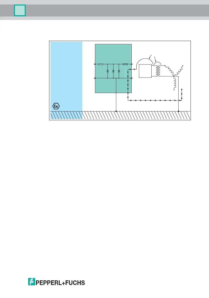
If the zener barrier is grounded and a fault occurs the zener diodes conducts. The
current is shunted to ground. The fuse opens.
Figure 3.4 Grounded zener barrier
The system must have its own independent ground conductor, through which no
supply system current flows.
The Z-system grounding is made by an integrated ground connection in the base
of each zener barrier. By connecting each zener barrier to the 35 mm DIN
mounting rail, the total system can be grounded via a single point. The following
figures show several grounding schemes.
• Equipotential bonding via DIN mounting rail
• Group grounding through insulated mounting
• Individual grounding through insulated mounting
Zone 0, 1, 2
Div. 1, 2
Fault
Transformer
Power supply
Fault current
Grounding
AC/DC
supply
voltage