
A
Allen SullivanAug 6, 2025
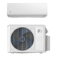
Why is my Perfect Aire 3PAMSHHQC18-MZO2 Air Conditioner not cooling or heating properly?
- CChristian HubbardAug 6, 2025
If your Perfect Aire Air Conditioner isn't cooling or heating properly, consider these potential causes and solutions: 1. The outdoor heat exchanger (like the condenser) might be dirty. Clean it to improve performance. 2. Indoor heating devices can affect cooling. Remove any such devices. 3. Poor air tightness can impact efficiency. Try to maintain better air tightness indoors. 4. Obstructions blocking the outdoor heat exchanger can hinder performance. Clear any blockages. 5. Incorrect temperature settings can cause issues. Double-check and adjust the temperature settings.