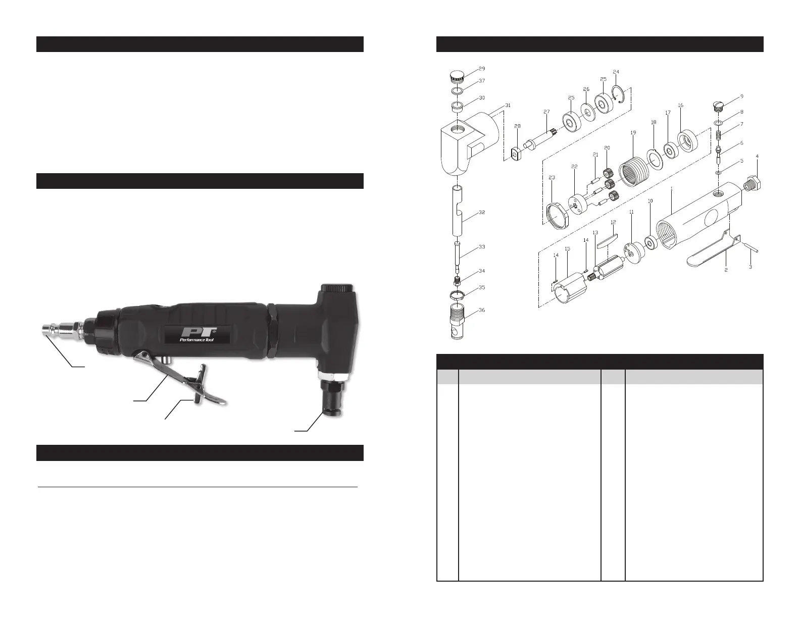
EXPANDED PARTS LIST
1. Hold nibbler square with work and start motor. Apply steady, even pressure. Do not
force. Too much pressure can cause punch to overheat and break. Tool little pressure
will keep nibbler from cutting and cause it to overheat.
2. Reduce pressure just before cutting through the work . When nibbler has completed
cut, remove from the work while the motor is running, then turn off the tool.
3. If the nibbler jams while cutting, release throttle immediately. Check to determine cause
of trouble before restarting motor. Do not attempt to free tool by starting and stopping
the motor.
OPERATION
Clean air of correct air pressure is recommended for the power supply for this tool. A
maximum of 90 PSI at the tool is recommended for most air tools of this class. Check
specifications section for recommended pressure. (Depending on length of air hose and
other circumstances, air pressure at compressor may need to be increased to 100 PSI to
ensure 90 PSI at the tool.)
Water in the air hose and compressor tank contributes to reduced performance and
damage of the air tool. Drain the air tank and filters before each use and as necessary to
keep the air supply dry.
Hose length over 25’ causes loss in line pressure. Increase hose I.D. or increase
compressor pressure to compensate for the pressure loss. Use an in-line pressure
regulator with gauge if air inlet pressure is critical.
AIR SOURCE
INSUFFICIENT POWER:
Probable Cause Solution
Dirty or clogged air passages......... Flush and lubricate tool, drain air tank and supply line
Insufficient air supply ...................... Increase line pressure, Make sure compressor
matches tool's air pressure and consumption needs
Air leakage ...................................... Use Teflon tape at all fittings and joints. Check tool for
worn or damaged O-rings & seals.
Worn/damaged wear & tear parts .. Replace as necessary.
Tool matching ................................. Be sure you are using a tool suited for the torque
requirements of the job at hand.
TROUBLESHOOTING
No. Description Qty.
1 Housing .................................... 1
2 Trigger ...................................... 1
3 Trigger Pin ...............................1
4 Air Inlet ..................................... 1
5 O-Ring ......................................1
6 Valve Stem ............................... 1
7 Spring.......................................1
8 O-Ring ......................................1
9 Screw Knob..............................1
10 Bearing.....................................1
11 Rear Plate ................................1
12 Blade ........................................4
13 Motor ........................................1
14 Pin ............................................2
15 Cylinder ....................................1
16 Front plate ................................1
17 Bearing.....................................1
18 Washer ..................................... 1
19 Gear Ring.................................1
No. Description Qty.
20 Idle Gear.................................3
21 Gear Pin .................................3
22 Gear Plate ..............................1
23 Clamp Nut ..............................1
24 Retainer .................................. 1
25 Bearing ...................................2
26 Washer ...................................1
27 Crank Shaft ............................1
28 Driving Bushing ......................1
29 Screw Knob ............................1
30 Bushing ..................................1
31 Nibble Head............................1
32 Slide Rod ................................ 1
33 Cutter ......................................1
34 Set Screw ...............................1
35 Clamp Nut ..............................1
36 Cutter Die ...............................1
37 O-ring .....................................1
38 Cutter ......................................2
EXPANDED PARTS LIST
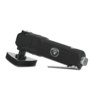
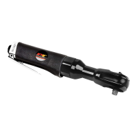
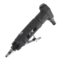
Punch
Safety Lever
Trigger Lever
Air Inlet
 Loading...