MAINTENANCE
1. Clean the outside of the press with dry, clean and soft cloth and periodically lubricate the joints and all moving parts
with a light oil as needed.
2. When not in use, store the press in a dry location with ram and piston fully retracted.
3. When press efficiency drops, purge the hydraulic system to eliminate any air in the system as described in 4.1.
4. Check the hydraulic oil: remove the oil filler nut on the pump, if it is not adequate, fill with high quality hydraulic jack oil
as necessary, then replace the oil filler nut, purge away air from the hydraulic system as described in 4.1
BEFORE FIRST USE
OPERATING INSTRUCTIONS
1. Note: Before first use of this product, purge away air from the hydraulic system: open the release valve by turning it coun-
terclockwise. Pump several full strokes to eliminate any air in the system.
2. Check all parts and conditions, if there is any part broken, stop using it and contact your supplier immediately.
WARNING!
Ensure that you read, understand and apply the safety instructions and warnings before use.
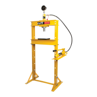
1. Place the heel block on press bed frame, then insert workpiece onto the heel block.
2. Close the release valve by turning it clockwise until it is firmly closed.
3. Pump the handle until serrated saddle nears workpiece.
4. Align workpiece and ram to ensure center-loading.
5. Pump the handle to apply load onto workpiece.
6. When work is done, stop pumping the handle, slowly and carefully remove load from workpiece
by turning the release valve counterclockwise in small increments.
7. Once ram has fully retracted, remove workpiece from bed frame.
Part No. Description Qty.
1. Pressure gauge 1
2. Nylon ring 1
3. Ram assy 1
4. Screw M6 1
5. Bolt M10 2
6. Upper plate 1
7. Upper round nut 1
8. Under plate 1
9. Saddle 1
10. Upper cross beam 2
11. Under round nut 1
PARTS LIST
Part No. Description Qty.
12. Bolt M12 X 30 14
13. Washer 12 22
14. Lock washer O 12 22
15. Nut M12 22
16. Pressure plate 2
17. Bed frame 1
18. Bed frame pin 2
19. Frame Post 2
20. Base plate 2
20A. Support Strap 4
21. Washer O 10 10
Part No. Description Qty.
22. Lock washer O 10 10
23. Nut M10 10
24. hose 1
25. Lower cross member 1
26. Pump bracket 1
27. Washer O 8 3
28. Bolt M8 X 16 3
29. Pump assy 1
30. Hose fitting 1