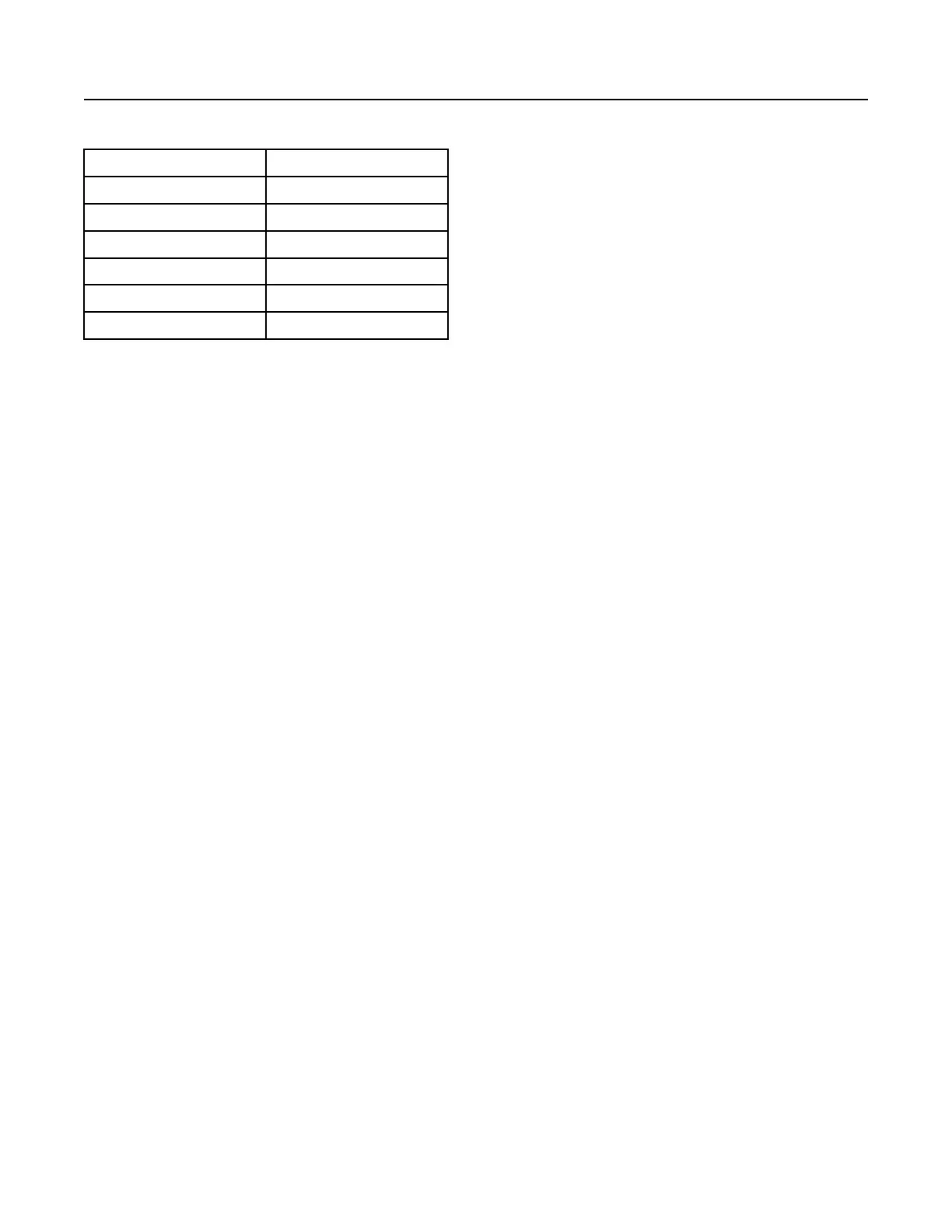
(Table 1, contd)
Aspiration Turbocharged aftercooled
Compression Ratio
16.5:1
Displacement 7.01 L (427.77 cubic inch)
Firing Order
1-5-3-6-2-4
Rotation (flywheel end)
Counterclockwise
Valve Lash Setting (Inlet) 0.35 mm (0.013 inch)
Valve Lash Setting (Exhaust) 0.35 mm (0.013 inch)
(1)
The operating rpm is dependent on the engine rating, the appli-
cation, and the configuration of the throttle.
Electronic Engine Features
The engine operating conditions are monitored. The
Electronic Control Module (ECM) controls the
response of the engine to these conditions and to the
demands of the operator. These conditions and
operator demands determine the precise control of
fuel injection by the ECM. The electronic engine
control system provides the following features:
• Engine monitoring
• Engine speed governing
• Control of the injection pressure
• Cold start strategy
• Automatic air/fuel ratio control
• Torque rise shaping
• Injection timing control
• System diagnostics
For more information on electronic engine features,
refer to the Operation and Maintenance Manual,
“Features and Controls” topic (Operation Section).
Engine Diagnostics
The engine has built-in diagnostics in order to ensure
that the engine systems are functioning correctly. The
operator will be alerted to the condition by a “Stop or
Warning” lamp. Under certain conditions, the engine
horsepower and the vehicle speed may be limited.
The electronic service tool may be used to display
the diagnostic codes.
There are three types of diagnostic codes: active,
logged and event.
Most of the diagnostic codes are logged and stored in
the ECM. For additional information, refer to the
Operation and Maintenance Manual, “Engine
Diagnostics” topic (Operation Section).
The ECM provides an electronic governor that
controls the injector output in order to maintain the
desired engine rpm.
Engine Cooling and Lubrication
The cooling system consists of the following
components:
• Gear-driven centrifugal water pump
• Water temperature regulator which regulates the
engine coolant temperature
• Gear-driven rotor type oil pump
• Oil cooler
The engine lubricating oil is supplied by a rotor type
oil pump. The engine lubricating oil is cooled and the
engine lubricating oil is filtered. The bypass valve can
provide unrestricted flow of lubrication oil to the
engine if the oil filter element should become
plugged.
Engine efficiency, efficiency of emission controls, and
engine performance depend on adherence to proper
operation and maintenance recommendations.
Engine performance and efficiency also depend on
the use of recommended fuels, lubrication oils, and
coolants. Refer to this Operation and Maintenance
Manual, “Maintenance Interval Schedule” for more
information on maintenance items.
SEBU8731-04
23
Product Information Section
Product Description