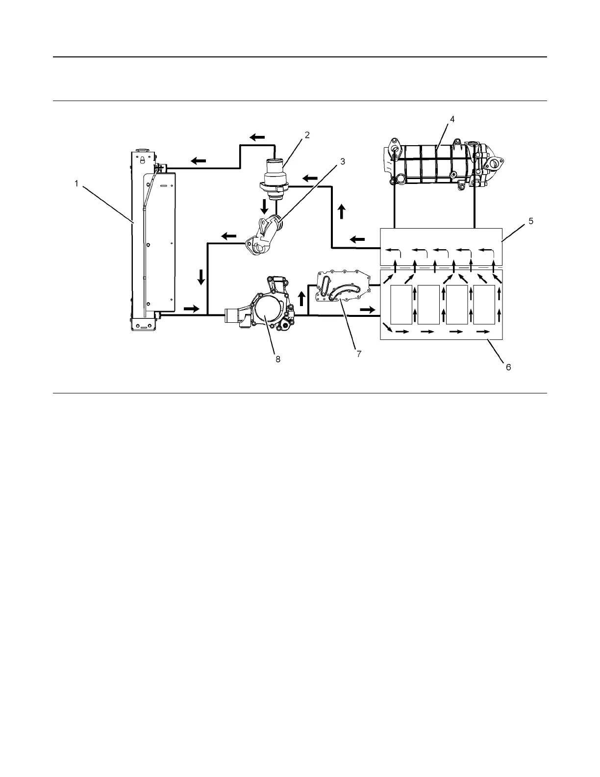
Coolant Flow
Illustration 30 g02332698
Typical example
(1) Radiator
(2) Water temperature regulator and
housing
(3) Bypass for the water temperature
regulator
(4) Exhaust gas cooler (NRS)
(5) Cylinder head
(6) Cylinder block
(7) Engine oil cooler
(8) Water pump
The coolant flows from the bottom of the radiator (1)
to the centrifugal water pump (8). The water pump (8)
is installed on the front of the timing case. The water
pump (8) is driven by a gear. The gear of the fuel
injection pump drives the water pump gear.
The water pump (8) contains a rotary seal that uses
the engine coolant as a lubricating medium. This will
ensure that an adequate sealing film is created. The
sealing film is maintained in order to reduce heat
generation. Heat that is generated by the rotating
sealing faces under normal operating conditions
causes a small flow of coolant to be emitted into a
chamber. The water pump (8) pumps the coolant
through a passage in the timing case to the front of
the cylinder block (6).
The coolant enters a passage in the left side of the
cylinder block (6). Some coolant enters the cylinder
block. Some coolant passes over the element of the
oil cooler (7). The coolant then enters the block (6).
Coolant flows around the outside of the cylinders
then flows from the cylinder block into the cylinder
head (5).
Some coolant flows through a cavity in the front of
the cylinder head (5). Some coolant is diverted into
the exhaust gas cooler (4) by a coolant pipe in the
rear of the cylinder head (5). The coolant then flows
out of the exhaust gas cooler (4) to the cavity in the
cylinder head (5).
36 UENR4490-01
Engine Operation
This document has been printed from SPI2. NOT FOR RESALE
 Loading...


