(7) Coolant temperature sensor
(8) Inlet manifold air temperature sensor
(9) Secondary speed/timing sensor
(10) Primary speed/timing sensor
(11) Fuel injection pump
(12) Suction control valve for the fuel
injection pump
(13) Fuel temperature sensor
(14) Electronic unit injectors
The ECM determines the quantity, timing, and
pressure of the fuel in order to be injected into the
fuel injector.
The ECM uses input from the sensors on the engine.
These sensors include the speed/timing sensors and
the pressure sensors.
The ECM controls the timing and the flow of fuel by
actuating the injector solenoid.
The amount of fuel is proportional to the duration of
the signal to the injector solenoid.
The ECM controls the fuel pressure by increasing or
decreasing the flow of fuel from the fuel injection
pump.
Fuel Injectors
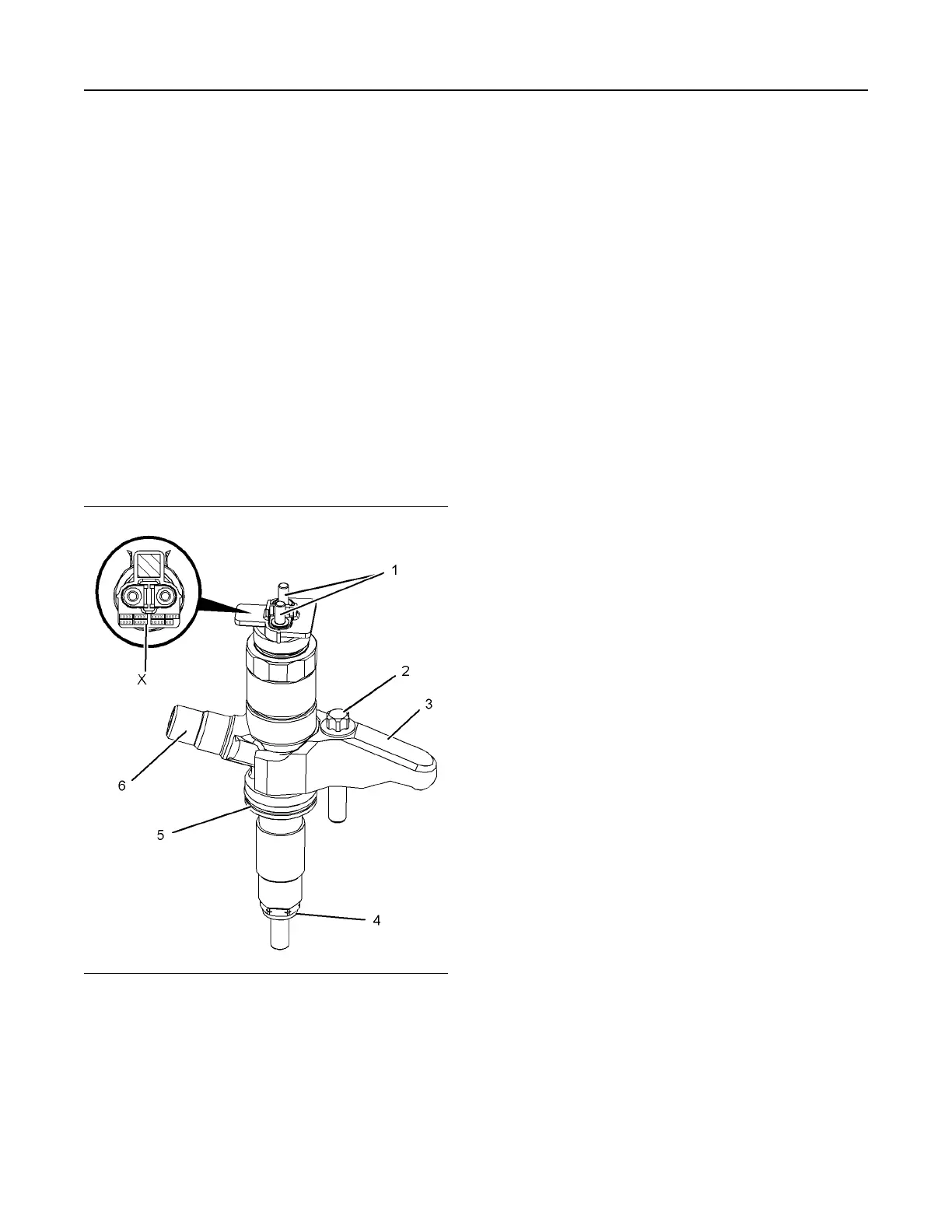
Illustration 39 g02290433
Typical example
(1) Electrical connections
(2) Bolt
(3) Clamp
(4) Combustion washer
(5) O-ring
(6) Fuel inlet
Note: If a replacement electronic unit injector is
installed, the correct injector code must be
programmed into the electronic control module. Refer
to Troubleshooting, “Injector Code - Calibrate” for
more information. The code that is required is located
at Position (X). Record Code (X) before the electronic
unit injector is installed.
The fuel injectors contain no serviceable parts apart
from the O-ring seal and the combustion washer. The
clamp and setscrew are serviced separately.
The pressurized fuel from the fuel manifold is injected
into the combustion chamber by the electronic unit
injector. The desired injection timing, injection
quantity and injection pattern are controlled by the
ECM depending on engine operating conditions.
The injection process is controlled using a two-way
valve. The supply of electrical current to the solenoid
controls the two-way valve. When the two-way valve
is not energized the out orifice is closed and there is
no fuel leak. In this condition the pressure in the
control chamber and the pressure at the nozzle
needle are the same. In this condition the spring
pressure on the command piston keeps the needle
closed.
When an injection of fuel is required, the electrical
current from the ECM charges the solenoid, which in
turn energizes the two-way valve and lifts the valve.
When the valve lifts the valve uncovers the out
orifice. The fuel starts to flow and reduces the
pressure in the control chamber. When the pressure
difference at the nozzle needle exceeds the
combined pressure of the control chamber pressure
and the spring pressure, the nozzle lifts to start the
injection process. The fuel coming out of the nozzle is
atomized and injected as a very fine spray.
When the injection needs to be stopped the electrical
current to the solenoid is cut off and the pressure
difference in the control chamber starts increasing.
The increased pressure difference stops the injection
process when the combined pressure exceeds the
nozzle pressure.
The electronic unit injectors can be instructed to
inject fuel multiple times during the combustion
process. A close pilot injection occurs before the
main injection. The close pilot injection helps to
reduce NOx and noise. The main injection period
helps to increase the torque of the engine. The after
injection period helps to reduce the amount of smoke
that is produced.
UENR4490-01 47
Engine Operation
This document has been printed from SPI2. NOT FOR RESALE





 To Next Page