EasyManua.ls Logo

Perkins 700 Series Repair Manual

Perkins 700 Series
206 pages
To Next Page IconTo Next Page
Page #1 background imageLoading...
Page #1 background image
i
Perkins 700 Series
Models UA, UB and UC
WORKSHOP MANUAL
Four cylinder naturally aspirated and turbocharged
diesel engines
Publication TPD 1392E, Issue 3.
© Proprietary information of Perkins Engines Company Limited, all rights reserved.
The information is correct at the time of print.
Published in February 2002 by Technical Publications.
Perkins Engines Company Limited, Peterborough PE1 5NA, England.
This document has been printed from SPI². Not for Resale

Table of Contents

Other manuals for Perkins 700 Series

Question and Answer IconNeed help?

Do you have a question about the Perkins 700 Series and is the answer not in the manual?

Perkins 700 Series Specifications

General IconGeneral
Engine TypeDiesel
Number of Cylinders4
Cooling SystemLiquid Cooled
AspirationTurbocharged
Emissions ComplianceTier 3/Stage IIIA

Summary

General information

Safety precautions

Details essential safety measures for operating and maintaining the engine.

Specifications

Basic engine data

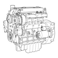
Presents fundamental specifications like cycle, cylinders, bore, stroke, and compression.

Data and dimensions

Provides detailed measurements and tolerances for engine components.

Recommended torque tensions

Lists standard torque values for various fasteners and components.

Cylinder head assembly

Valve tip clearance

Procedure for checking and adjusting valve tip clearance.

Cylinder head setscrews

Steps for removing and fitting cylinder head setscrews, including torque specifications.

Piston and connecting rod assemblies

Crankshaft assembly

Crankshaft

Steps for removing the crankshaft.

Timing case and drive assembly

Cylinder block assembly

Cylinder block bores

Procedure for inspecting cylinder bores for wear and damage.

Engine timing

To set approximately number 1 piston to TDC on the compression stroke

Procedure to set piston number 1 to Top Dead Centre on the compression stroke.

Fuel injection pump timing

Procedure for checking and adjusting fuel injection pump timing (spill timing).

Lubrication system

Fuel system

Fuel injection pump

Steps for removing and fitting the fuel injection pump.

Cooling system

Flywheel and housing

Electrical equipment

Special tools

Rack position tool

Tool used for setting the maximum fuel position of the fuel control rack.

Related product manuals