EasyManua.ls Logo

Perkins M300TI User Manual

Perkins M300TI
86 pages
To Next Page IconTo Next Page
Page #1 background imageLoading...
Page #1 background image
TPD1317e Contents
Perkins Sabre Marine Engines
Installation Manual
M300Ti 6 Cylinder turbocharged, intercooled, diesel engine for
pleasure boat applications
M265Ti 6 Cylinder turbocharged, intercooled, diesel engine for
pleasure boat applications
M225Ti 6 Cylinder turbocharged, intercooled, diesel engine for
pleasure boat applications
M215C 6 Cylinder turbocharged, intercooled, diesel engine for
commercial applications
M185C 6 Cylinder turbocharged, intercooled, diesel engine for
commercial applications
M135 6 Cylinder naturally aspirated, diesel engine for pleasure boat
applications
M130C 6 Cylinder naturally aspirated, diesel engine for commercial
applications
M115T 4 Cylinder turbocharged diesel engine for all applications
M92 4 Cylinder naturally aspirated diesel engine for all
applications
M92B 4 Cylinder naturally aspirated diesel engine for all
applications
Publication TPD 1317e, Issue 10
Published in May 2007 by Sabre Engines Ltd, Wimborne, Dorset, England. BH21 7PW
Tel: +44(0)1202 893720 Fax: +44(0)1202 851700 Email: post @sabre-engines.co.uk
Website: www.Perkins-Sabre.com
Question and Answer IconNeed help?

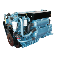
Do you have a question about the Perkins M300TI and is the answer not in the manual?

Perkins M300TI Specifications

General IconGeneral
BrandPerkins
ModelM300TI
CategoryEngine
LanguageEnglish

Summary

Installation Points Overview

Engine Mounting Overview

Details engine mounting angles, brackets, and bearers.

Propeller Shafts & Couplings

Information on propeller shafts and gearbox output couplings.

Engine Controls and Ancillary Systems

Engine Controls by Model

Details on engine speed and gearbox engagement for various models.

Chapter 1: Engine Mounting

1.1 Installation Angles

Permissible heel angles for engine installation.

Chapter 3: Exhaust Systems

3.1 Wet Exhaust Systems

General arrangement and requirements for wet exhaust systems.

3.2 Dry Exhaust Systems

Design considerations for dry exhaust systems.

Chapter 5: Engine Cooling Systems

5.1 Raw Water Systems

Guidelines for providing a separate sea water system for each engine.

5.2 Keel Cooling Statement

Statement that keel cooling is not offered for M300Ti/M265Ti models.

5.3 Keel Cooling Systems (M225Ti/M215C/M185C)

Requirements for keel cooling systems for specific engine models.

5.5 Keel Cooling Systems (M115T/M92/M92B)

Requirements for keel cooling systems for M115T/M92/M92B.

Chapter 6: Fuel Systems

6.1 Fuel Connections

Thread details for engine fuel pipe connections.

6.2 Typical Fuel Systems

Ideal system layout and features for fuel tanks.

Chapter 7: Engine Electrical Systems

7.1 Engine Wiring Looms

Connects starter, alternator, senders, and switches to a multiway connector.

7.2 Fuseboard

Location and identification of fuses on the fuseboard.

7.6 Battery and Starter Cables

Specifications for battery performance and cable sizing.

Electrical System Diagrams

Wiring Loom Circuit Diagrams

Lists circuit diagrams for various engine models and configurations.

Chapter 7: Battery and Starter Cables

Battery Performance Standards

Explains BS3911 and SAE J537 battery rating methods.

Battery Specifications by Model

Table detailing battery requirements for different models and temperatures.

Chapter 8: Engine Controls

Related product manuals