Do you have a question about the Perkins New 1000 Series and is the answer not in the manual?
Essential safety guidelines for operating and maintaining the engine.
Guidelines and recommendations for safely lifting engine components.
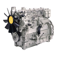
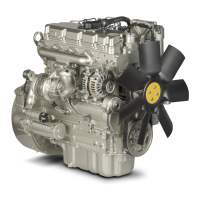
Key technical data for Perkins 1000 Series engines, including cylinder count and bore.
Detailed specifications and measurements for cylinder head components.
Standard torque values for common fasteners like setscrews, nuts, and pipe unions.
Component-specific torque settings for engine assembly and disassembly.
Procedures for removing, fitting, dismantling, and inspecting the rocker assembly.
Instructions for checking and adjusting valve tip clearances for 4-cylinder engines.
Procedures for removing and fitting the cylinder head assembly.
Procedures for removing, fitting, and inspecting valves and valve springs.
Methods for inspecting and correcting the cylinder head for distortion and wear.
Procedures for removing and fitting big end bearings.
Procedures for removing and fitting pistons and connecting rods.
Procedures for removing and fitting one-piece and two-piece rear oil seal assemblies.
Procedures for removing and fitting main bearings with the crankshaft in position.
Procedures for removing and fitting the crankshaft.
Procedures for removing and fitting the fuel pump gear.
Procedures for removing and fitting the timing case.
Procedures for dismantling and assembling the cylinder block.
Methods for setting the number 1 piston to Top Dead Center on the compression stroke.
Procedure for checking the timing of the fuel injection pump.
Procedures for removing and fitting the turbocharger.
Chart to assist in diagnosing common turbocharger faults.
Procedures for removing and fitting the lubricating oil pump.
Procedures for renewing fuel filter elements (separate and canister types).
Procedure for eliminating air from the fuel system.
Procedures for removing and fitting the flywheel.
Catalog of specialized tools required for engine service and repair.
| Engine Type | Diesel |
|---|---|
| Cylinder Arrangement | Inline |
| Number of Cylinders | 4 or 6 |
| Cooling System | Liquid Cooled |
| Aspiration | Turbocharged |