X
●Avoid potential personal injury or property damage! Do not use a drill for tightening the
lag screws! Only use a socket wrench. DO NOT over-tighten the lag screws [A1]. Tighten
the lag screws [A1] only until they are pulled firmly against the wall plate.
●DO NOT USE ANCHOR [A2] FOR THIS STEP!
●Ensure the arm assembly / wall plate [01B] is securely fastened
to the wall before continuing on to the next step.
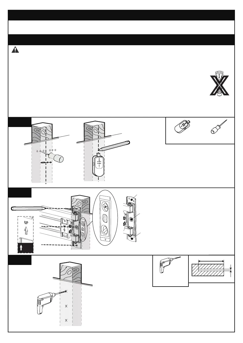
● Any material covering the wall must not exceed 5/8”(16mm)
● Nominal wood stud size: common 2 x 4”(51 x 102mm) minimum 1½ x 3½”(38 x 89mm).
● Stud center must be verified.
WARNING:
Step 3 Attach the Arm Assembly / Wall Plate [01B] to Wall
For wood stud installation, follow STEP 3A
For concrete installation, follow STEP 3B
Step 3A Wood Stud Option
5/32” (4mm)
2 3/4” (70mm)
3A-1
3A-2
3A-3
Position the arm assembly / wall
plate [01B] at your desired height
and line up the holes with your
stud center line. Level the wall
plate and mark the holes.
Drill 3 pilot holes using a 5/32” (4mm)
diameter drill bit. Make sure the depth
is not less than 2 3/4” (70mm).
Use a stud finder (not included) to
locate wood studs or use an awl
(not included) to verify the edges.
Mark the edge and center locations.
UP
1
2
3
OR
Stud Finder
(Not lncluded)
Awl
(Not lncluded)
OR
Electric Drill
(Not lncluded)
01 02 03 04 05 06 07 08 09 10 11
12 13 14 15 16 17 18 19 20 21 22
23 24 25 26 27 28 29 30 31 32 33
34 35 36 37 38 39 40 41 42 43 44
45 46 47 48 49 50 51 52 53 54 55