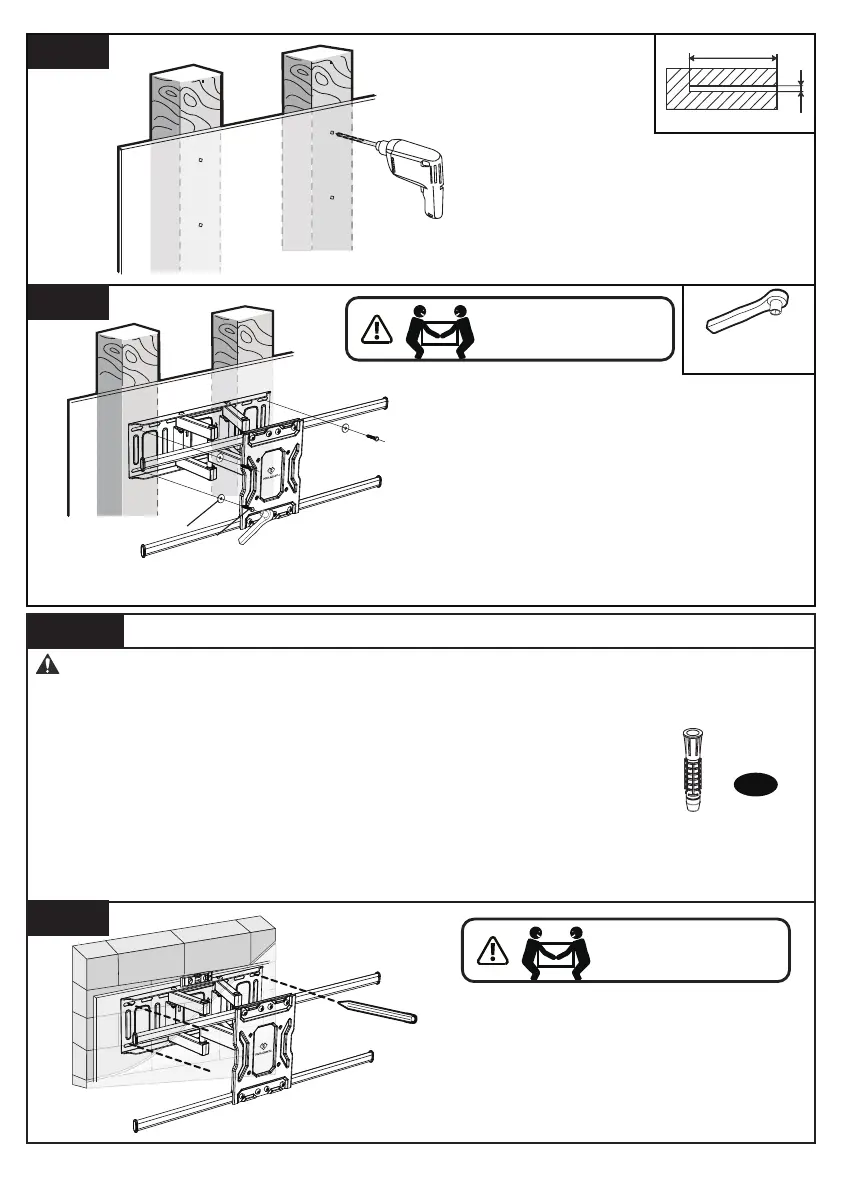
7/32 in.(ø5.5mm)
2 9/16 in.(65mm)
Drill 4 pilot holes using a
7/32 in.(5.5mm) diameter drill
bit. Make sure the depth is not
less than 2 9/16 in.(65mm).
3A-3
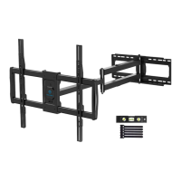
Step 3B Solid Concrete or Concrete Block Option
WARNING:
● Avoid potential personal injury or property damage! DO NOT over-tighten the lag
screws [A1]. Tighten the lag screws [A1] only until the washers [A2] are pulled firmly
against the wall plate.
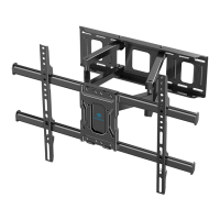
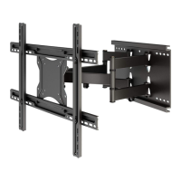
● Ensure the arm assembly/wall plate [05] is securely fastened to the
wall before continuing to the next step.
● Any material covering the wall must not exceed 5/8 in. (16 mm)
● Mount the arm assembly/wall plate [05] directly onto the concrete surface
● Minimum solid concrete thickness: 203 mm (8 in.)
● Minimum concrete block size: 203 x 203 x 406 mm (8 x 8 x 16 in.)
● Never drill into the mortar between blocks
Wall Anchor
A3
33/64 in.(13mm)
Socket Wrench
Install the arm assembly/wall
plate [05] using lag screws [A1]
and washers [A2]. Tighten the
lag screws [A1] only until the
washers [A2] are pulled firmly
against the wall plate.
3A-4
A2
A1
Position the arm assembly/wall
plate [05] at your desired
height, level the wall plate and
mark the pilot hole locations.
3B-1
HEAVY! You may need
assistance with this step.
HEAVY! You may need
assistance with this step.
08