This document provides installation instructions for the PERLESMITH PSLLK1 TV wall mount.
Function Description:
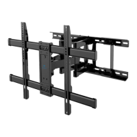
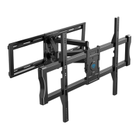
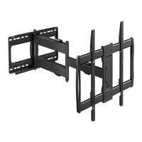
The PERLESMITH PSLLK1 is a TV wall mount designed to securely attach a television to a wall. It consists of a wall plate that mounts to the wall and TV brackets that attach to the back of the television. The TV then hangs onto the wall plate, providing a stable and space-saving mounting solution. The design incorporates a locking mechanism to ensure the TV remains securely in place once mounted.
Before installation, it is crucial to check all package contents against the supplied parts and hardware list to ensure everything is undamaged. Any damaged or defective parts should not be used, and replacements can be requested from customer service at supportus@perlesmith.com. Not all included parts and hardware may be used. It is essential to read all instructions carefully before attempting installation. If any part of the instructions is unclear or if there are concerns, customer service should be contacted. The product may contain moving parts, so caution is advised during handling. This product should not be used for any purpose or in any configuration not explicitly specified in the instructions. The manufacturer disclaims liability for injury or damage resulting from incorrect assembly, mounting, or use. A critical safety warning is DO NOT INSTALL INTO DRYWALL ALONE. For more product and company information, users can visit www.perlesmith.com.
Technical Specifications (Derived from instructions):
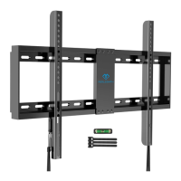
- Wall Plate Dimensions: The wall plate is assembled from two halves (01 and 02). The overall length for stud mounting is indicated as 16 inches (406mm) to 24 inches (609mm) for stud spacing.
- TV Hole Pattern (VESA Compatibility):
- 100 mm ≈ 4 in.
- 200 mm ≈ 7 7/8 in.
- 300 mm ≈ 11 3/4 in.
- 400 mm ≈ 15 3/4 in.
- 600 mm ≈ 23 6/10 in.
- Maximum TV height compatibility: 400mm / 16 in.
- Maximum TV width compatibility: 600mm / 23.6 in.
- Mounting Surface Compatibility:
- Wood Stud Walls:
- Any material covering the wall must not exceed 5/8 in. (16 mm).
- Nominal wood stud size: common 2 x 4 in. (51 x 102 mm) minimum 1½ x 3½ in. (38 x 89 mm).
- Stud center must be verified.
- Pilot hole diameter: 5.5 mm.
- Pilot hole depth: Not less than 60 mm.
- Fasteners: Lag Bolts ST8X65 (A1) and Washers M8 (A2).
- DO NOT USE ANCHOR [A3] FOR THIS STEP.
- Solid Concrete or Concrete Block Walls:
- Any material covering the wall must not exceed 5/8 in. (16 mm).
- Mount the wall plate directly onto the concrete surface.
- Minimum solid concrete thickness: 203 mm (8 in.).
- Minimum concrete block size: 203 x 203 x 406 mm (8 x 8 x 16 in.).
- Pilot hole diameter: 10 mm.
- Pilot hole depth: Not less than 70 mm.
- Never drill into the mortar between blocks.
- Fasteners: Lag Bolts ST8X65 (A1), Washers M8 (A2), and Wall Anchors (A3).
- Hardware for Attaching TV Brackets to TV:
- Washers (05): M6/M8 (x4)
- Spacers (06) [If necessary]: 2.5mm (x8), 10mm (x4), 22mm (x4)
- TV Screws (07) [Only one size fits your TV]:
- M6 x 15mm (x4)
- M6 x 35mm (x4)
- M8 x 25mm (x4)
- M8 x 35mm (x4)
- M8 x 50mm (x4)
- Supplied Parts:
- Wall Plate (01) x1
- Wall Plate (02) x1
- TV Bracket (03) x1
- TV Bracket (04) x1
- Level x1
Usage Features:
- TV Screw Selection: The first step involves checking the TV hole pattern and selecting the appropriate TV screws (07) and washers (05). Only one screw size will fit the TV.
- Spacer Selection (Optional): Spacers (06) are provided for specific TV types:
- Not necessary for flat TVs with no obstructions.
- Recommended for TVs with inset holes, cable interference, or rounded backs to create extra space between the TV and the bracket.
- Securing TV Brackets: The TV brackets (03 and 04) are secured to the back of the TV using the selected screws (07) and washers (05), with spacers (06) if needed.
- Wall Plate Assembly: The left half of the wall plate (01) is secured to the right half (02) using a pre-assembled screw [S]. It's important to tighten until snug, but not overtighten.
- Wall Plate Installation:
- Wood Stud Option: Requires a stud finder, tape measure, pencil, drill, 5.5mm wood drill bit, and hammer (not included). Users locate wood studs, mark edge and center locations, position the wall plate, level it, mark holes, drill pilot holes, and then install the wall plate using lag bolts (A1) and washers (A2). Anchors (A3) are explicitly not to be used for wood stud installation.
- Solid Concrete or Concrete Block Option: Requires a tape measure, pencil, drill, 10mm concrete drill bit, hammer, and 13mm socket wrench (not included). Users position the wall plate, level it, mark holes, drill pilot holes (avoiding mortar), use a hammer to knock anchors (A3) flush into the wall, and then install the wall plate using lag bolts (A1), washers (A2), and anchors (A3).
- Mounting the TV:
- The TV, with attached brackets (03 and 04), is hung onto the wall plate (01 and 02).
- A locking mechanism is engaged by pulling a rope down and pressing the bottom of the TV into the wall plate until the latches lock the TV brackets. The rope is then released.
- Caution: This step is marked as "HEAVY!" and may require assistance.
- Removing the TV: To remove the TV from the wall plate, the rope is pulled down to release the latches.
Maintenance Features:
The manual does not explicitly detail maintenance features. However, implicit maintenance involves:
- Regularly checking the security of the wall plate and TV brackets.
- Ensuring all screws and bolts remain tightened to the specified snugness.
- Contacting customer service for replacement parts if any components become damaged or defective.