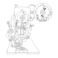
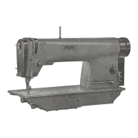
When slots n and o (Photo 19) point lengthwise of the arm, the valves
are
open.
By turning them
either
woy,
the oil flow
can
be
regulated
as
desired
or shut
off
completely. It is
recommended,
however,
normally to
leave
valve
n
open
and
thus to
ensure
proper
lubrication
of
the
head
parts
ond
both
top
shaft
bearings.
22.
Regulating
the
Flow of
Oil
to
the
Head
Parts
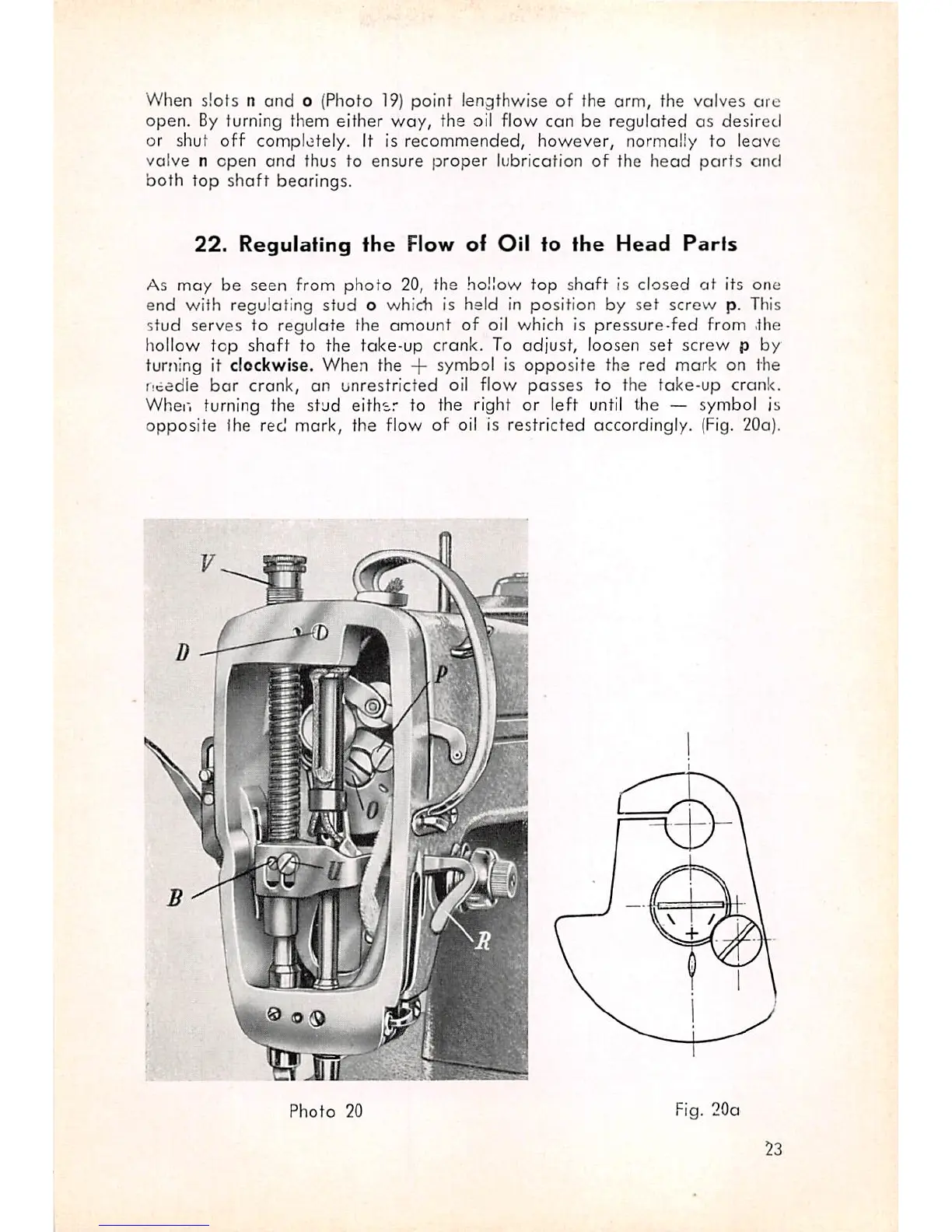
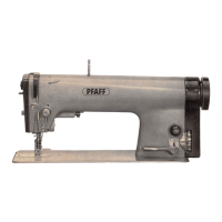
As may be seen from
photo
20, the hollow top
shaft
is closed
at
its one
end with regulating stud o which is held in position by
set
screw p. This
stud serves to regulate the
amount
of oil which is pressure-fed from .the
hollow
top
shaft
to the
take-up
crank.
To
adjust,
loosen
set
screw
p by
turning it clockwise. When the + symbol is
opposite
the red mark on the
needle
bar
crank,
an
unrestricted
oil flow
passes
to the fake-up crank.
Whei'i turning the
stud
either
to the right
or
left until the — symbol is
opposite
the red mark, the flow of oil is restricted accordingly. (Fig. 20a).
Photo
20
Fig.
20a
23