7-14-44
5
5
6
7
6
1
2
3
4
2
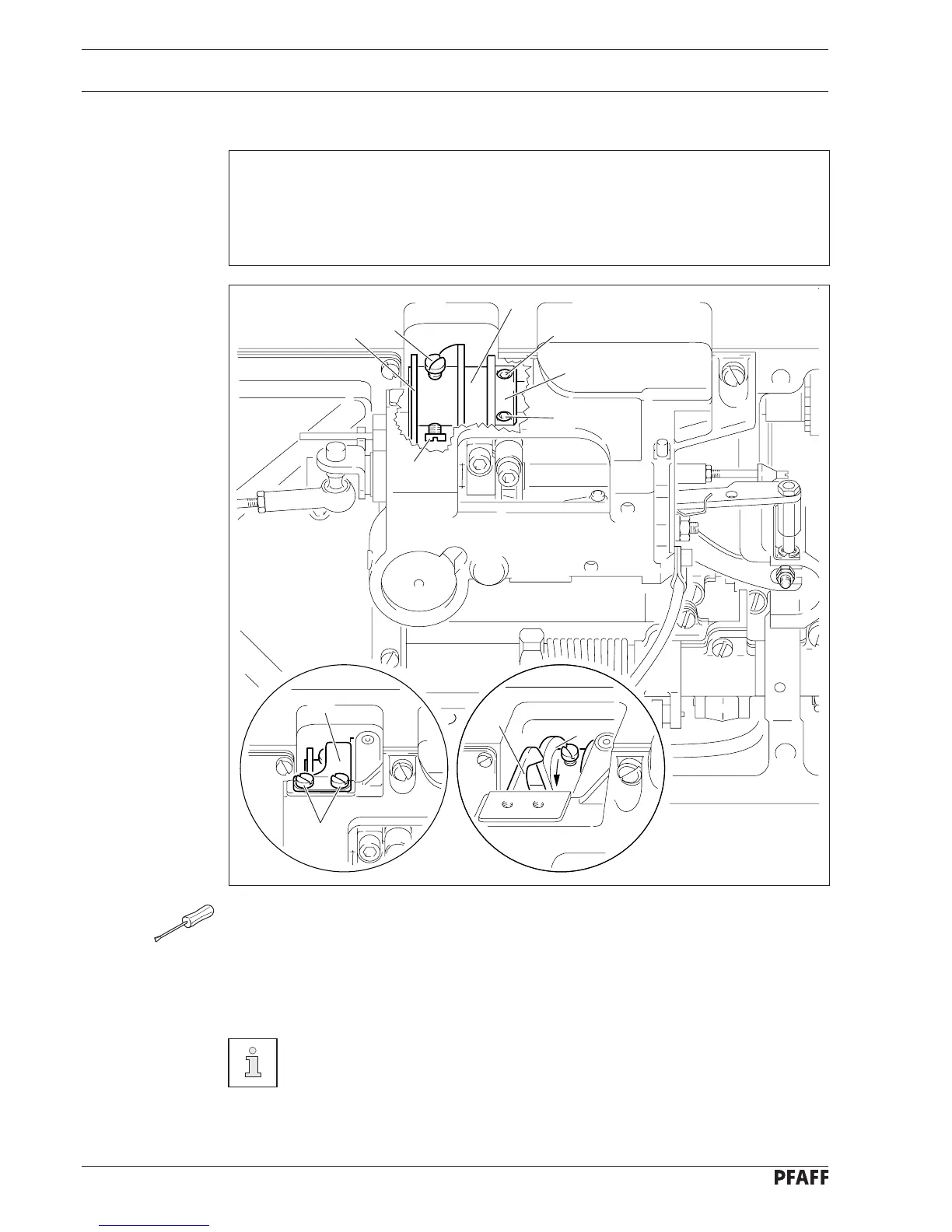
Fig. 2 - 02
● Unscrew screw 3 and remove retaining spring 4 together with the cover washer.
● Loosen screws 5 and 6.
● Turn control cam 1 in accordance with requirement 1 and position it in accordance with
requirement 2.
● Tighten screws 5.
● Push retaining collar 7 onto control cam 1 and tighten screws 6.
1
Retaining spring 4 stays removed for the following adjustments.
Requirement
With the needle bar at tdc (hole 2):
1. the beginning of the highest point of the lobe of control cam 1 must be underneath the
point of pawl 2,
2. the right hand side of the lobe must be flush with pawl 2.