75
Chapter 9: Support
PIN NOMENCLATURE / FUNCTION
P ISO GND / Ground / Shield (for signals: A, B, C, R, and V)
R Pre-Trigger In / MemGate In
Pre-Trigger In / Places camera into the ‘Ready’ state or
‘Capture’ mode with dtection of TTL (falling edge) pulse.
Mem-Gate In / Active-low isolated input.
Capture cable = Red
S IRIG Out (Unmodulated) / IRIG-B timecode output.
Swings to RS-232 levels of +/- 9V
Capture cable = Blue
T GenLock / Synchronizes playback to a properly
terminated (75-ohm) video signal (not exceeding +1.56V
maximum), utilizing a composite video inbound signal,
or synch live video, by synchronizing the SDI outputs
to the GenLock signal.
U Receive Data (RS-232) / standard RS-232 level.
V Ready / Isolated collector output with 1k pull-up.
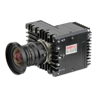
Phantom vxx12
Viewfinder Connector
PIN NOMENCLATURE / FUNCTION
1 GND / Power Ground
2 GND / Power Ground
3 PB HD Blue Channel
4 PR HD Red Channel
5 Y HD Green Channel
6 GND / Power Ground
7 +12V Positive 12 VDC / 1.5 Amp
Component VF port
7-pin Fischer part # S103.A057
Capture port (continued)