Chapter 10: FAQs & Support | 71
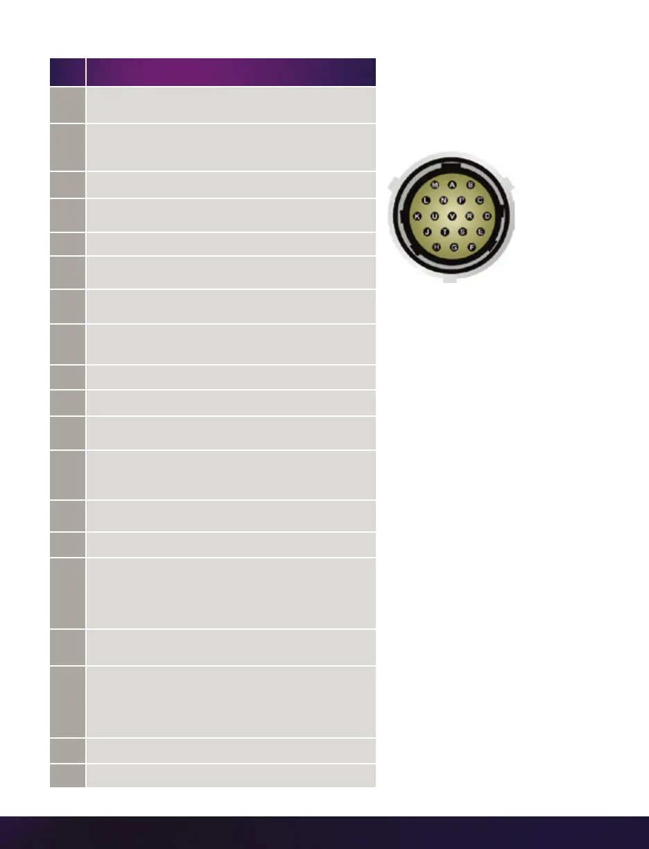
CAPTURE CONNECTOR
Capture port
19-pin Part #PTO6A-14-19S
PIN NOMENCLATURE/FUNCTION
A
Event-In / active-low isolated input; signal must be active
when strobe is high, and be 30 µs long minimum.
B
Trigger / active-low isolated input. Can be activated by a
switch to ground. The trigger pulse needs to be at least
three microseconds long. Capture cable = Red.
C
Strobe Out / Isolated collector output with 1k pull-up.
D
IRIG-In (Unmodulated) / IRIG-B timecode input.
Capture cable = White.
E
IRIG GND
F
Video Out (Composite) / Standard (non-isolated) 75-ohm
output level. Capture cable = Green.
G
Video GND (Composite) / Ground / Shield
(for signals: F and T).
H
Serial (RS-232) Ground / Should only be connected to
properly earthed equipment. (Serial ports are not isolated.)
J
Chassis GND
K
Transmit Data (RS-232) / standard RS-232 level.
L
+12-30VDC / DC output (0.5A amp max.). Typically
used to power Break-out-Boxes.
M
Power GND / isolates power input and acquisition control
signals from system ground to avoid system ground loops
only and should not be subjected to high voltages.
N
Auto-Trigger Output / Pulled low when an Auto-Trigger
condition is detected. Capture cable = Black.
P
ISO GND / Ground / Shield (for signals: A, B, C, R, and V)
R
Pre-trigger In / MemGate In
Pre-trigger In / Places camera into the ‘Ready’ state or
‘Capture’ mode with detection of TTL (falling edge) pulse.
Mem-Gate In / active-low isolated input.
Capture cable = Red.
S
IRIG Out (Unmodulated) / IRIG-B timecode output. Swings
to RS-232 levels of +/- 9V. Capture cable = Blue.
T
GenLock / Synchronizes playback to a properly
terminated (75-ohm) video signal (not exceeding +1.56V
maximum), utilizing a composite video inbound
signal, or sync live video, by synchronizing the SDI
outputs to the GenLock signal.
U
Receive Data (RS-232) / standard RS-232 level.
V
Ready / Isolated collector output with 1k pull-up.
 Loading...