OperatingInstructions&PartsManual
HorizontalRotaryTables
DividingPlates
Pg. 8
TroubleshootingChart
Symptom PossibleCause(s) CorrectiveAction
Handwheelrotates:
Tabledoesnotrotate
1.Key(Ref.No.32)ismissing
1.InsertKey
2.WormShaftdisengaged 2.Engagewormshaft
(seeoperation)
Handwheelwillnotrotate 1. Hold‐downclampsare
tootight
2.Locknuttootight
(seemaintenance)
3.Tableneedlubrication
1. Loosenhold‐downclamps
2. Adjustlocknutproperly
3. Lubricateproperly
(seeMaintenance)
WormShaftwillnotengage
Table
Eccentricsleevecannotrotate
properly
Properlyadjustthreadedpinand
Setscrew(seemaintenance)
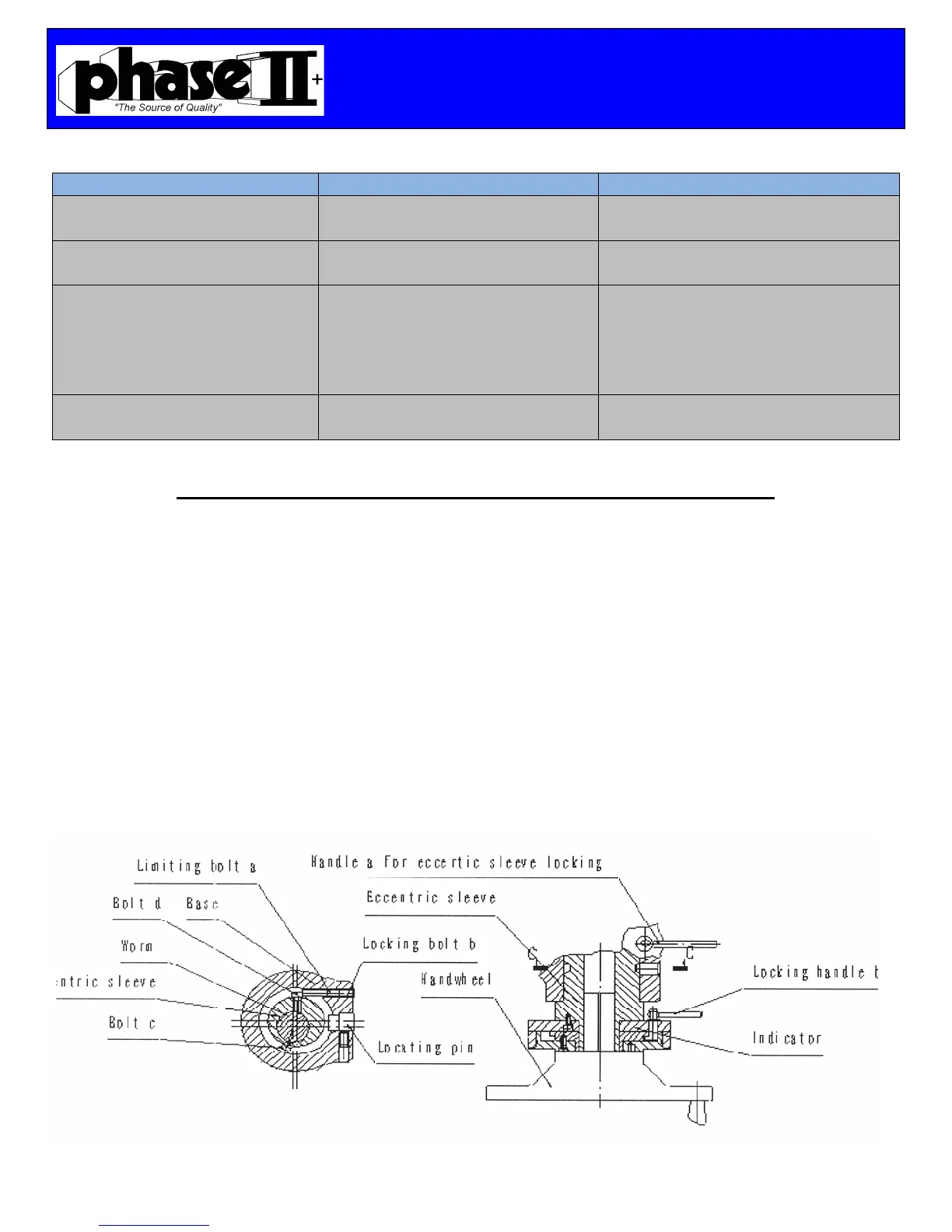
WormGear/EccentricSleeveAdjustment
First Loosen Handle A for the eccentric sleeve lock and proceed to unscrew Bolt B.
Screw clockwise the Limiting Bolt A to adjust the mesh of the worm gear to the table top gear.
At this time, rotate the handle wheel clockwise and counterclockwise to ensure the mesh of the
worm gear is within 6° and then tighten the Locking Bolt B and then clamp the Handle A to
lock the eccentric sleeve.
Screw counterclockwise the Limiting Bolt A to reduce the mesh and proceed to rotate the
handwheel to ensure the mesh of the worm gear is within 6° and then tighten Locking Bolt B.
Rotate the Indicator counterclockwise until the Bolt C is touching the Locating Pin. This
procedure has just disengaged the worm gear. Rotate the indicator clockwise until Bolt D is
touching Bolt A. Now the worm gear is engaged.
 Loading...