23 | P a g e
3.3 Change Parameter Values
The Main Menu item, 1 CHANGE PARAMETER VALUES, leads to several sub-menus that contain adjustable
operating parameters. These parameters provide basic functions such as motor overload protection and
advanced features that allow customized operation of the drive to fit the specific application.
Section 4 contains a complete list of the parameters along with a description of their function and instructions
on setting them.
3.4 Read Measured Values
The display can provide a variety of measured values related to the performance of the drive and its load such
as currents, horsepower, and power factor. To read measured values:
1. Press the HOME key to access Main Menu items, and then scroll with arrow keys until 3 READ
MEASURED VALUES appears on the display.
2. Press ENTER to access this menu item.
3. Use the UP and DOWN arrow keys to scroll through the various values that you wish to read.
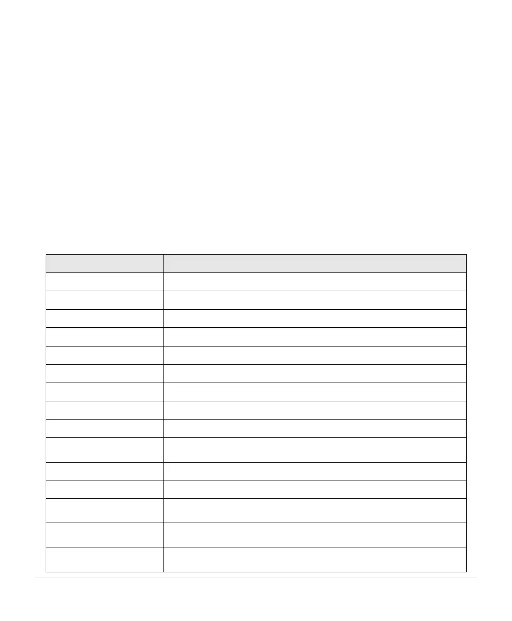
Table 8 – Measured Values
DESCRIPTION OF MEASURED VALUE
Three-phase output currents, measured in Amps (A)
Output measured in horsepower (HP)
Output measured in kilowatts (kW)
Output measured in kilovolt amperes (kVA)
Power factor of the motor load
Output frequency in Hertz (Hz)
Voltage of the DC bus, measured in Volts DC (VDC)
Input voltage, measured in Volts AC (VAC)
Input current measured in Amps (LHX systems only)
Indicates model number of the product and the firmware version of the
Interface and Driver digital signal processors (DSP).
ON/OFF status of the remote switch circuits AUX1 and AUX2
ON/OFF status of the remote switch circuits AUX3 and AUX4
Measures the 0-10 VDC analog control voltage between Control
Terminals for 0-10 VDC input.
Measures 4-20 mA analog control current on I1 and I2Control Terminals
for analog current input.
Displays the current RPM of the fan load. Parameter 1.1.28 MOTOR
RPM must be programmed for this to display a reading.