41 | P a g e
Table 19 – 1.3 Interface Parameters
DEFAULT [UNITS]
(MIN - MAX)
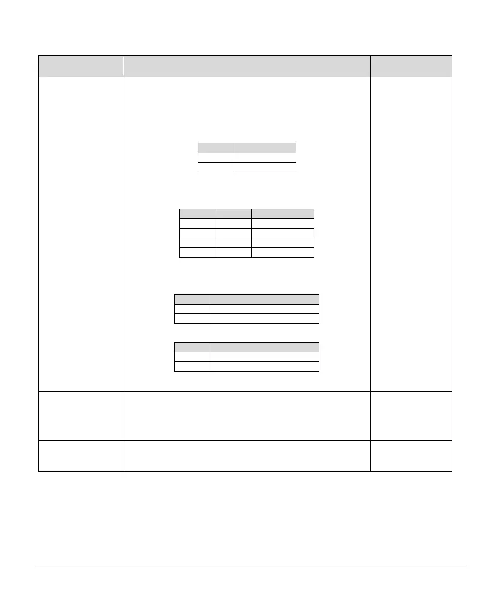
1.3.1 System Config
(see Section 5.5,
System Configuration
for detailed
information)
Sets the system configuration.
0 = ON/OFF control using AUX1 and AUX2. Both AUX1 and AUX2
must have a contact closure to run.
1 = Analog Constant Pressure control.
2 = Analog Constant Pressure with redundant sensors and up to
two psi setpoints. Control setpoint will change based on the states
of AUX3, as shown in the table below.
3 = Analog Constant Pressure with redundant sensors and up to
four psi setpoints. Control setpoint will change based on the states
of AUX3 and AUX4, as shown in the table below.
4 = Speed control proportional to an analog signal set point (speed
potentiometer).
5 = Analog constant pressure with HOA and speed pot
6 = Analog constant pressure (4-20 mA only) with dual sensors
See Section 5.5, for more details.
Determines what parameters are shown or hidden. Simple will be
adequate for most applications but more complex programming
requires additional parameters to be visible. Parameters visible in
Standard mode will be followed by “$” on the display. Parameters
visible in Advanced mode will be followed by “@” on the display.
1.3.3 Disable Manual
Mode
Disables manual operation of the drive through the keypad.
Operating states are limited to AUTO and OFF. YES = MANUAL
mode disabled