56 | P a g e
Terminals. If the primary sensor fails, the backup sensor will automatically take over control of constant
pressure at the same settings.
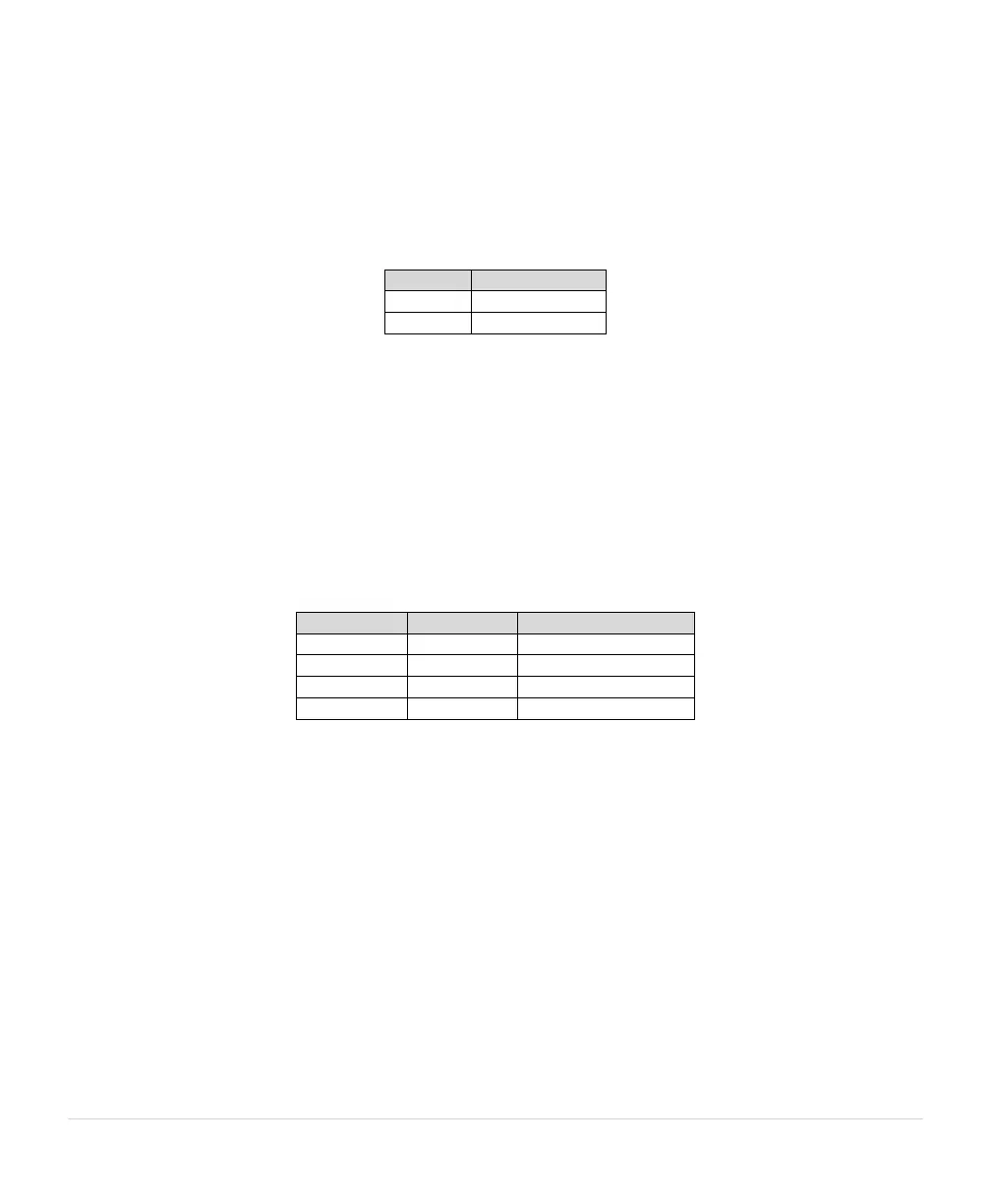
Up to two control setpoints can be used in this configuration. Enter the value of these set points in the
Constant Pressure parameter, 1.4.1 PSI SETPOINT 1 – 1.4.2 PSI SETPOINT 2. The table below show
what setpoint the system will follow based on the configuration of the AUX3. AUX1 and AUX2 must also
be closed for the system to run.
Table 25 – System Configuration 2 Setpoints
• 1.3.1 System Configuration = 3: Analog Constant Pressure with redundant sensors and up to four
PSI Setpoints. This configuration allows the use of two 4-20 mA transducers. The primary sensor is
connected to the I1+ and I1- Control Terminals, with the backup sensor connected to the I2+ and I2- Control
Terminals. If the primary sensor fails, the backup sensor will automatically take over control of constant
pressure at the same settings.
Up to four control setpoints can be used in this configuration. Enter the value of these set points in the
Constant Pressure parameter, 1.4.1 PSI SETPOINT 1 – 1.4.4 PSI SETPOINT 4. The table below show
what setpoint the system will follow based on the configuration of the AUX3 and AUX4 terminals. AUX1
and AUX2 must also be closed for the system to run.
Table 26 – System Configuration 3 Setpoints
• 1.3.1 System Configuration = 4: Speed Pot Control. Use this setting for motor speed control by a
potentiometer or an external 0-10 VDC source connected to the 0-10 VDC Control Terminals. Refer to
Figure 14 for a diagram illustrating connection of the potentiometer or the voltage source to Control
Terminals. The drive will ignore the DC analog signal until it reaches a value proportional to the speed set
by the parameter, 1.1.1 MIN FREQUENCY, which has a factory default setting of 30 Hz. For speed control
across the full-scale range of the analog signal, set 1.1.1 MIN FREQUENCY to the minimum value of 5 Hz.
AUX1 and AUX2 must be closed to run in this System Configuration.
• 1.3.1 System Configuration = 5: Analog Constant Pressure with HOA and Speed Potentiometer. This
setting allows the user to either turn the motor off, control motor speed with a potentiometer, or operate in
analog constant pressure mode using an HOA switch. Access to the keypad is not required to operate in
this mode. A mechanical HOA switch changes the state of AUX1 and AUX3 Control Terminals to change to
mode of operation in this configuration. A potentiometer is connected to the 0-10 VDC control Terminals, a
4-20 mA analog transducer is connected to the I+ and I- Control Terminals, and a double pole, triple throw
HOA switch is connected to AUX1 and AUX3 Control Terminals.