69 | P a g e
In Multiplex control, the Master VFD might not always be the drive that is operating. The point of a multiplex
system is to rotate the use of each available VFD. This is done so that a single drive or pump does not degrade
at a faster rate than other drives or pumps in that system. The Master VFD will decide when to stage or
destage a VFD. The first pump to be staged in, and the last pump to be destaged, is called the Default VFD.
Multiplex Setup
System configuration must be set to one of the constant pressure modes when using multiplex control. See
Section 5.5, System Configuration, for details. Multiplex control is enabled when 1.5.1 NUMBER LAG PUMPS
is greater than 0, and 1.4.41 DUPLEX CYCLE TIME is greater than 0.
Programming Steps:
1. Use the keypad to navigate to 1.5.1 NUMBER LAG PUMPS and use the arrow keys to set the
number of auxiliary drives in the system.
2. Navigate to 1.4.41 DUPLEX CYCLE TIME, use the arrow keys to set how often the Default drive
position will change.
3. If necessary, adjust the remaining Lead/Lag parameters after reading the following description of
their functions, or after operating conditions dictate.
In Multiplex control, the Master VFD will utilize the Lead/Lag Parameters and logic similar to lead/lag control
in order to decide when to turn on/off a VFD. More detail on the logic behind these decisions will be given in
a later section.
It is recommended to run all auxiliary pumps on VFDs, otherwise pressure instability may occur. The Primary
Auxiliary Pump could turn on/off resulting in the system pressure oscillating from (1.4.1 ANALOG SETPOINT
1 – 1.5.15 STAGE ANALOG LAG) to (1.4.1 ANALOG SETPOINT 1 + 1.5.16 DESTAGE ANALOG LAG).
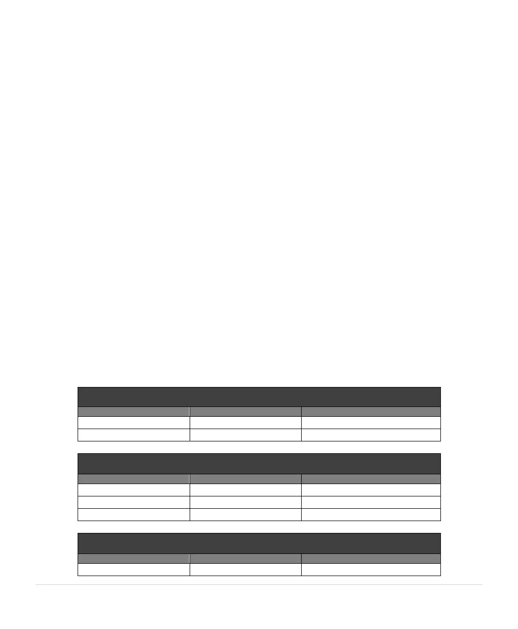
The Master VFD stages in VFDs in a different order depending on which VFD is the Primary. When the Master
VFD is not the Primary, it will ALWAYS be the second drive to be staged in. The tables below will illustrate the
order of the VFDs to be staged or destaged for different values of 1.5.1 NUMBER LAG PUMPS.
The Primary drive position will rotate based on the parameter 1.4.41 DUPLEX CYCLE TIME.