6CP100/50-10
3-3
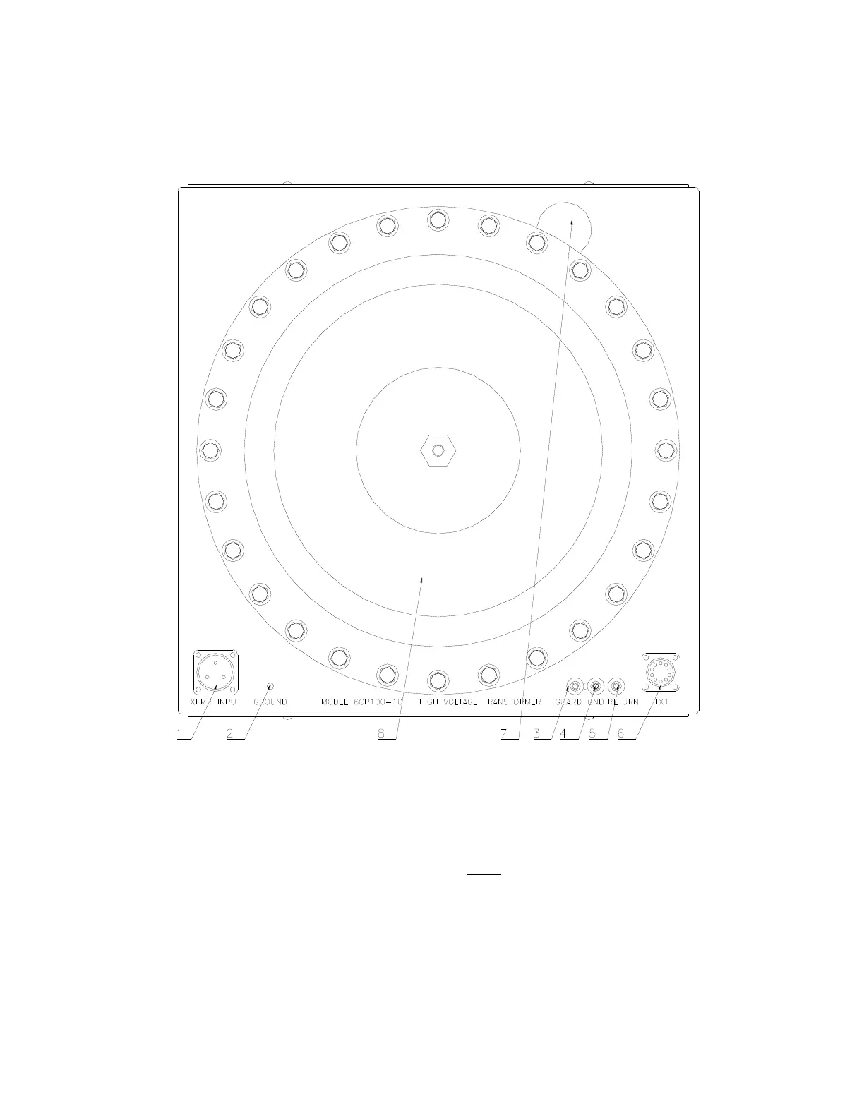
CONTROLS AND INDICATORS
High Voltage Transformer
Figure 3-2
The following descriptions are keyed to Figure 3--2:
1. Power Connector
Connect the Power Cable from ‘Output to Transformer’ connector on control box at this point.
2. High Voltage Unit Ground Point
A Ground cable from facility ground or earth ground must be connected here.
3. Guard Binding Post (GRD)
Currents associated with this connection bypass the current meter (meter bypass connection). See
Section 5 for more information on these connections.
4. Ground Binding Post with Jumper Clip (GND) - This binding post is connected to ground. See
Section 5 for more information on these connections.
NOTE: The Jumper Clip must always be connected from Ground to either Return or Guard.
 Loading...