6CP200/100-10
4-1
SECTION 4: INITIAL SET-UP--MECHANICAL
1. Set up object under test.
2. The area to be used for the test must provide sufficient mechanical and electrical clearances. The
approximate weight of each section is available from the nameplates or the Specification page.
3. If the unit is to be operated indoors, be sure the floor will be strong enough to support the unit. If operating
outdoors, the site for the base must be capable of supporting the unit without any settling that would tilt the
assembly.
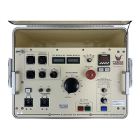
4. Position the High Voltage Transformer Modules, High Voltage Divider,3 and Control Unit as necessary for
operation. The Control Unit may be operated from either cart or any flat desk or floor surface.
NOTE: For parallel operation, the two transformer modules must be placed a small distance apart with
the base openings facing the same direction. Transportation strap must be removed from Top Module.
For series operation, base must be removed from Top Module. Remove 100kV electrode on the
Bottom Module. Cylinders should then be stacked and bolted together.
5. Clean High Voltage Modules using nothing stronger than ordinary household cleaner to remove all traces
of any surface contamination. This cleaning should also include the High Voltage Electrodes.

 Loading...