6CP200/100-10
3-1
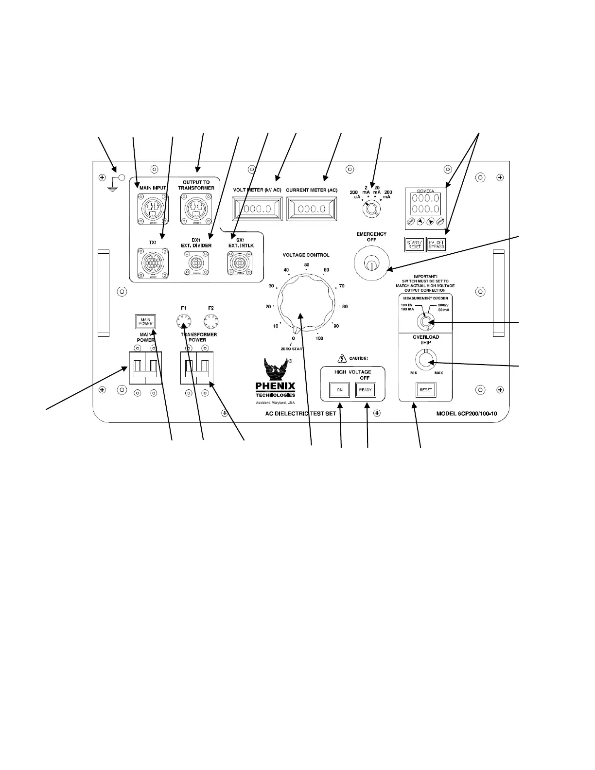
SECTION 3: CONTROLS AND INDICATORS
Control Panel
Figure 3-1
Descriptions are keyed to Figure 3-1
1. Main Power Circuit Breaker.
2. Main Power.Indicator
3. Transformer Power Circuit Breaker.
4. F1, F2 Control Power Fuse.
5. Measurement Divider Switch. Selects proper overload and voltmeter circuitry for the HV output
terminal being used. Match switch setting to output being used on HV transformer.
6. Overcurrent Trip. Use for presetting desired Overcurrent trip setting. Range approximately 10-110%
of rated current.
7. Reset. Will light when Overcurrent Trip setting is exceeded. Push to reset. Lamp must be
extinguished for HV ON.

 Loading...

