6CP200/100-10
4-2
INITIAL SET-UP--ELECTRICAL
1. Grounding Connections:
Use one of the supplied ground wires for making the ground connection between the control box
and the ground stud on the base of the Bottom Module.
Use another supplied ground wire to connect the facility ground to the Bottom Module ground stud.
If operating the Modules in parallel, use the paralleling cable to ground the Module bases together.
Use the last supplied ground cable to ground the HV Divider to the Bottom Module ground stud.
Connect the test specimen’s “low side” or ground to the ground stud on the Bottom Module using
the supplied return lead.
2. If the external interlock function is to be used, remove the jumper on the male cable end of the SX1
connector, and connect the external security circuit or footswitch at these points.
WARNING:
Ground the output of the High Voltage Transformer until set-up is complete! Be sure the Main
Power Circuit Breaker is in the OFF position before proceeding. This equipment should only be
operated by personnel familiar with High Voltage Testing and Safety Procedures.
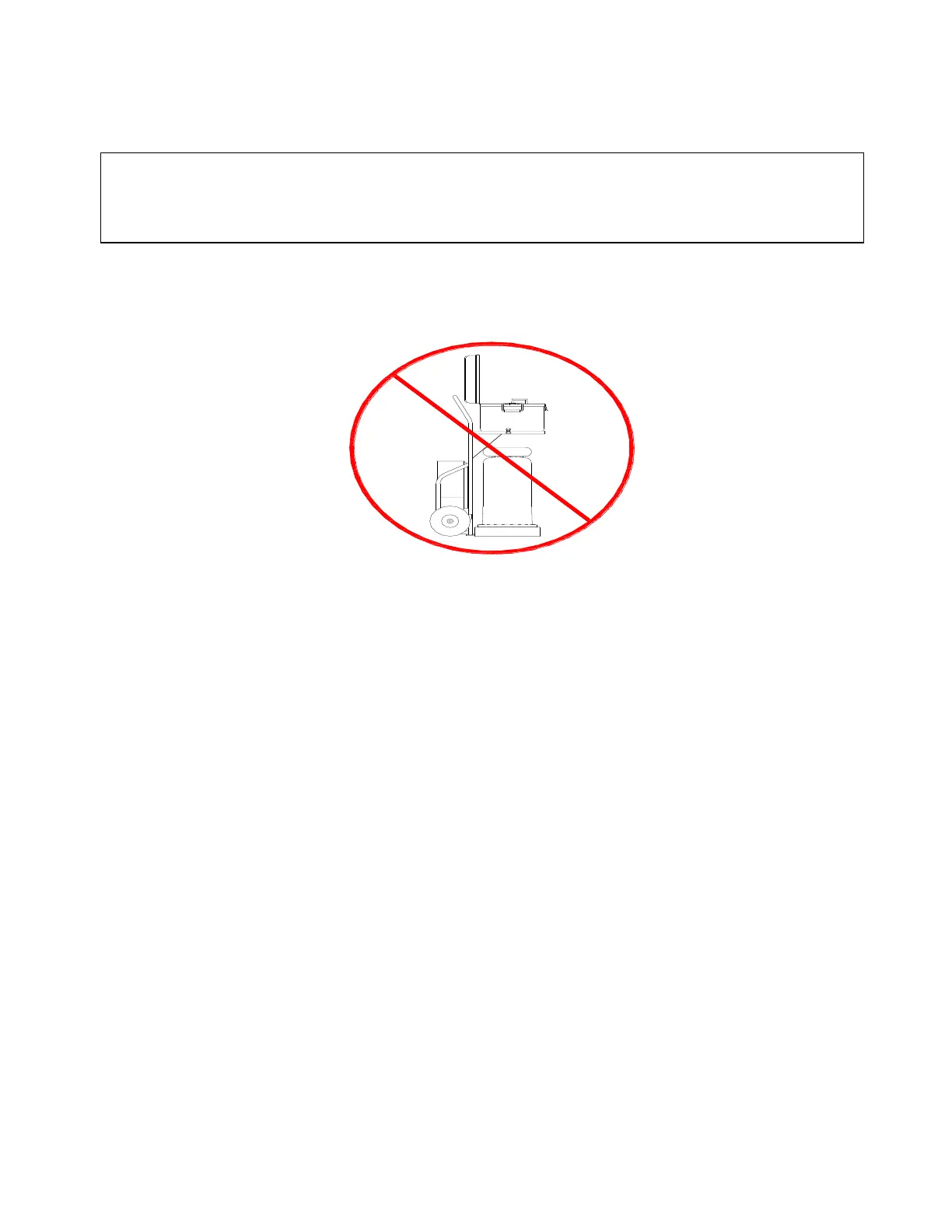
WARNING !
DO NOT OPERATE THE TEST SET
WITHOUT REMOVING HIGH-VOLTAGE
TRANSFORMER FROM THE CART.
THE HIGH-VOLTAGE TRANSFORMER
MUST BE POSITIONED A SAFE DISTANCE
FROM PERSONNEL AND OTHER OBJECTS.

 Loading...

