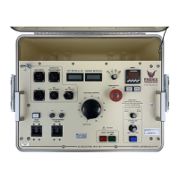
6CP200/100-10
6-2
CALIBRATION
3. Overcurrent
This calibration should not need adjustment (factory adjusted). If the Overcurrent Circuit is out of
calibration, perform the following steps. To recalibrate the Overcurrent Circuit with the High Voltage Unit it
will be necessary to connect an 4 nanofarad capacitor rated at 100 kVAC or higher to the 100 kV /100 mA
output of the High Voltage Unit. If the capacitor is isolated from ground at the low potential end, the low
potential end can be connected to the RTN post. The Guard Post Jumper may be connected to GRD
(Guard Mode). If the low potential end of the capacitor is grounded, the Ground Post Jumper must be
connected to RTN post.
a. Set front panel Measurement Divider switch to 100 kV/100mA. When current trip dial is set to
minimum (1) current trip level should be approx. 10 mA. When dial is set to maximum (11) trip
level should be approx. 110 mA.
b. Set the Overload Trip potentiometer (R15) on the front panel to "1" and the Current Range
switch to 200 mA.
c. Turn on HV On and adjust the output current slowly until 10% of rated current
is displayed on the current meter (10 mA).
d. Adjust potentiometer R69 until the Reset lamp illuminates and
high voltage is shut off.
e. Set the Overcurrent Trip potentiometer (R15) on the front panel to "11."
f. Turn on HV On and adjust the output current slowly until 110% of rated current is
displayed on meter (110 mA).
g. Adjust potentiometer R72 until the Reset Lamp illuminates and
high voltage is shut off.
h. Repeat steps "b" through "g" if necessary until both settings are calibrated
4. Range Overcurrent. R235 sets an overcurrent for the ranges and should be set to trip at approximately
112% of full range current on medium range setting with current trip potentiometer set at “11.”
5. Voltage offset adjustment (R113):
The voltage offset should be done with the voltage output lead connected to board ground. This typically
can be done by connecting the output to the guard terminal. Once connected, the offset should be adjusted
until the output meter reads nearest to zero. This offset adjustment should be done before adjustments to
the voltage ranges are made. Test point T10 may also be used to make this adjustment.
6. Current offset adjustment (R77):
The current offset should be done with the current input connected to board ground. This typically can be
done by placing a jumper from the guard to the return terminal. Once jumped, the offset should be adjusted
until the output meter reads nearest to zero. This offset adjustment should be done before adjustments to
the current ranges are made. Test point T37 may also be used to make this adjustment.

 Loading...