6-1
SECTION 6: CALIBRATION
All calibrations have been done at the factory. Periodic calibration of the output voltmeter and output
currentmeter should be done annually.
NOTE: Refer to Electrical Diagram Section for schematics pertaining to the model number of your test set.
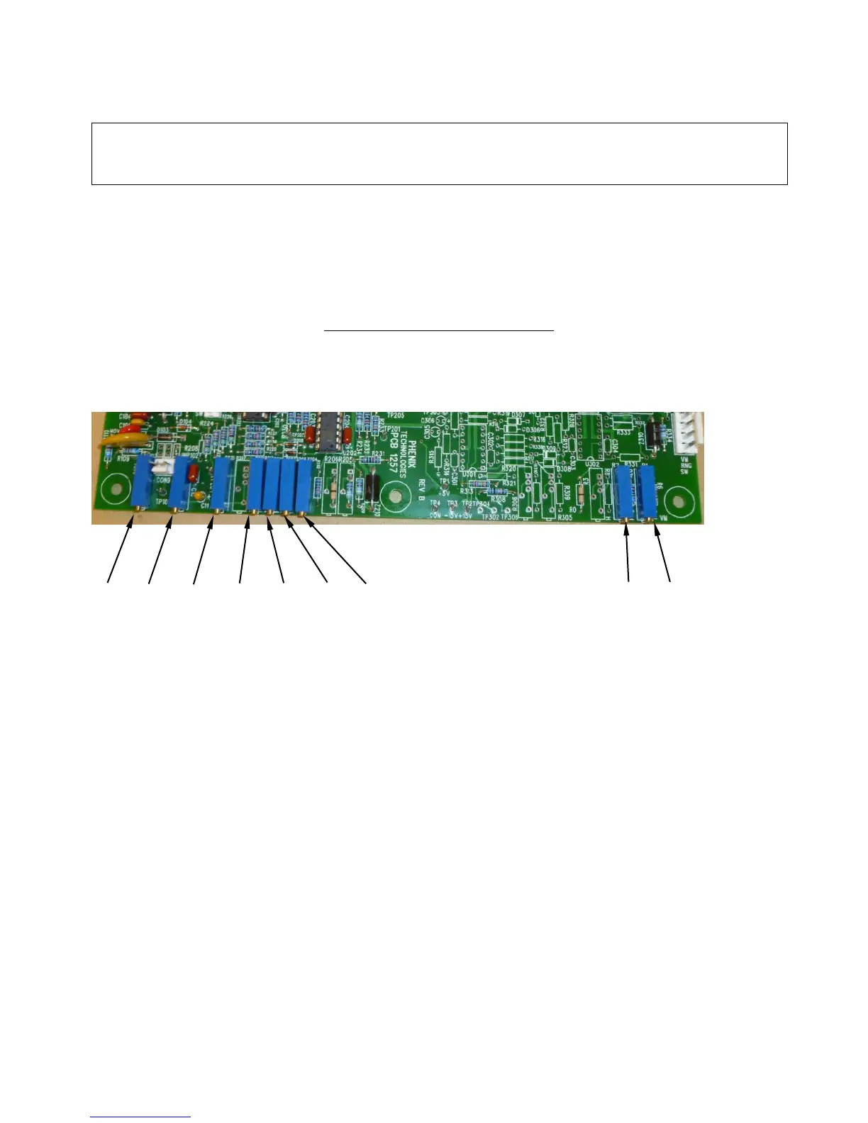
Locating the Calibration Adjustments
The calibration points are shown in the following diagram.
1. Output Voltmeter
Connect a precision high voltage voltmeter across the output to ground on low range. Raise the output to
approximately 80% of range. Adjust the reading on the panel meter (M1) by means of potentiometer R1
to a corresponding reading. Check Linearity and calibration at various other main points of the range
such as 20%, 40%, 60%, 100%. Repeat for High range, adjusting R2.
CAUTION:
Calibration should only be done by persons familiar with High Voltage testing and safety
procedures.