DCD 4100-10
2-2
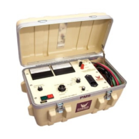
CONTROLS AND INDICATORS
CONTROL PANEL (Cont’d)
11. Output Voltage Control. Turn clockwise to increase output of test set. This control must be in the full
counter-clockwise position (Zero Start) in order to turn High Voltage On. Under normal circumstances,
Voltage Control should always be returned to zero and voltage displayed on the voltmeter allowed to
decay to zero before pressing High Voltage Off.
12. ANALOG CURRENT INDICATOR. Meter displays current from 0-100% of range to give visual indications
of capacitive charging conditions or to show changing current conditions that are not easily determined
from digital meters.
13. CURRENTMETER. Displays current out of High Voltage Lead (#16) or into Return terminal depending
upon mode of measurement
14. VOLTMETER. Displays voltage output of test set in kilovolts.
15. VOLTMETER RANGE SELECTOR. Rotate to appropriate setting for test voltage.
16. CURRENTMETER RANGE SELECTOR. Rotate to desired range. With capacitive loads, selector will
normally be placed in highest current range and then ranged lower as appropriate.
17. GUARD TERMINAL. Connect to Ground terminal (#13) with Grounding Clip for Guard Mode operation.
Connect currents that need to bypass the currentmeter to this point. Low potential side of specimen must
be isolated from ground to use this mode, and will be connected to Return post. See section on
Return – Ground – Guard for more information.
18. GROUND (GND) TERMINAL. Connects to facility ground. See (#12), (#14) and (#15) for more
information.
19. GROUNDING CLIP. The Grounding Clip must always be connected from the Ground post to either the
Return post or the Guard post. Do not operate the unit with the clip disconnected.
See Section 5 on Return – Ground – Guard for more information.
20. RETURN (RTN) TERMINAL. Connect to Ground terminal (#13) with grounding clip for normal operation.
Always connect low potential side of test specimen to this point. This is the metered connection point for
measuring current. This mode must be used if low potential side of test object is grounded or has a ground
reference. See section on Return – Ground – Guard for more
information.
21. HV OUTPUT LEAD. This lead is always attached to the high potential side of the specimen under test.